0577-67975099
 QQ
QQ WeChat
 邮箱
邮箱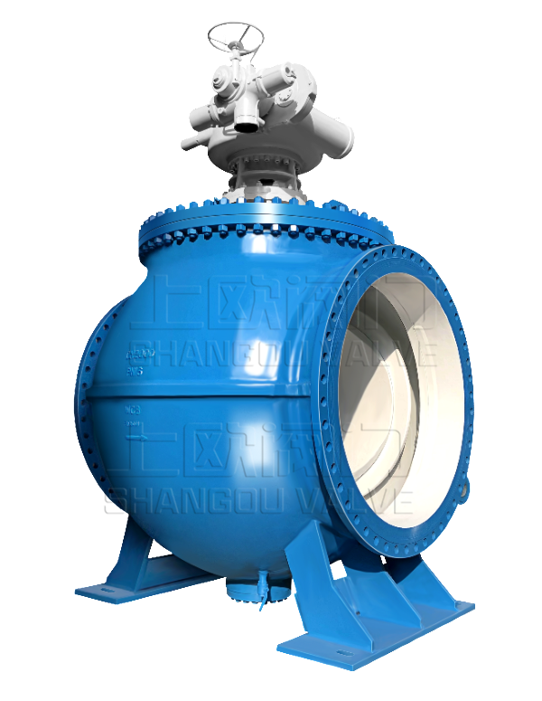


Telephone:
0577-67975099
 Location:Home > Product Center > Ball Valve > Q644F、Q645F-16CCast steel ball valve with three-way flange
 Telephone:
0577-67975099
Telephone:
0577-67975099
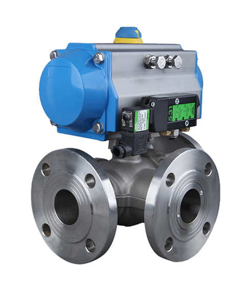
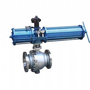
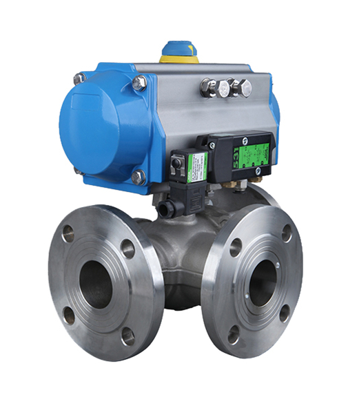
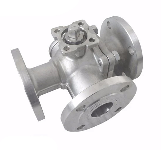
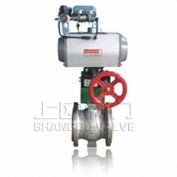
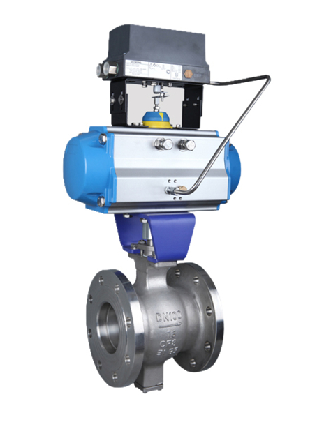
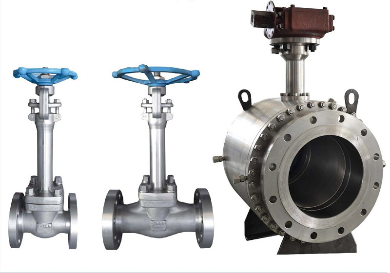
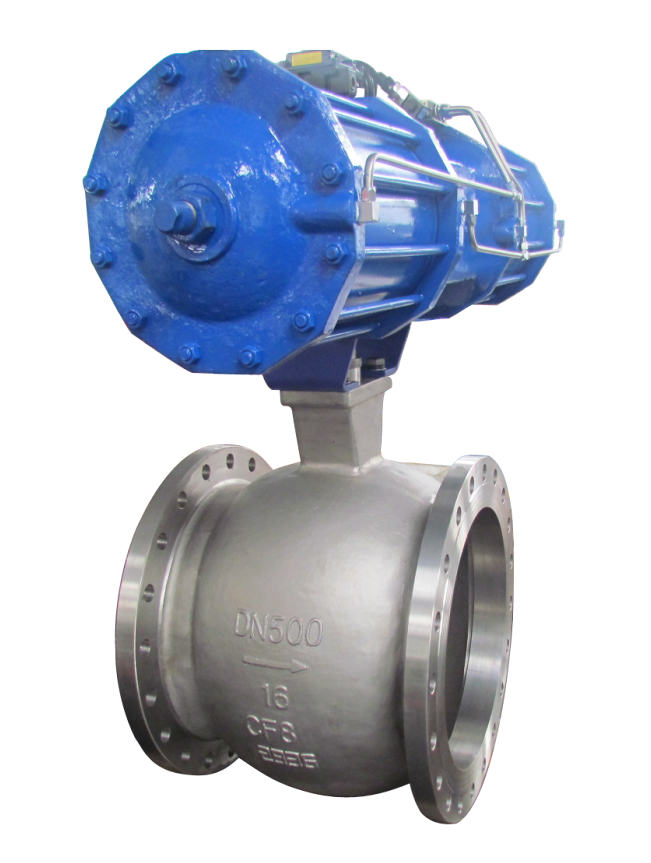
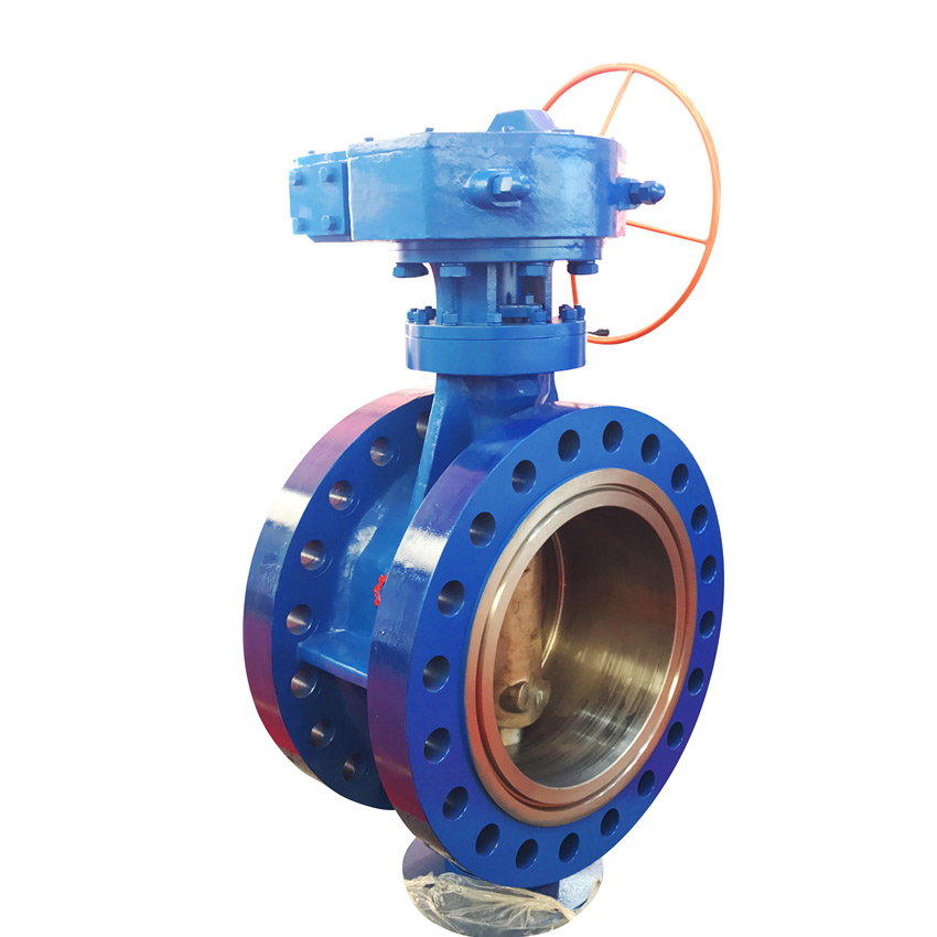
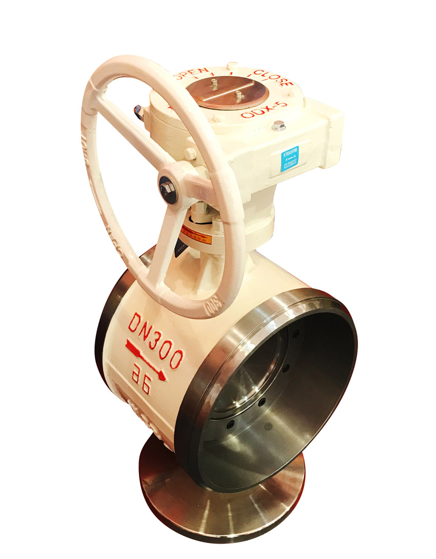
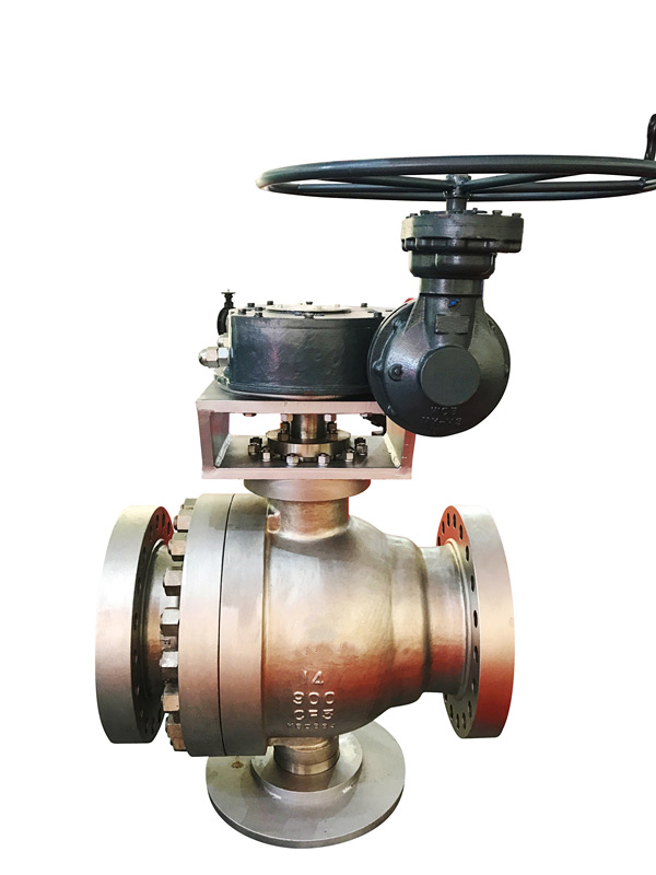
Q644F、Q645F-16CT-type pneumatic three-way flange cast steel ball valve can be divided into T-type pneumatic three-way ball valve and L-type pneumatic three-way ball valve. T-type three-way ball valve can make three orthogonal pipelines connect with each other and cut off the third channel, which plays the role of shunt and confluence. The L-type three-way ball valve can only connect two mutually orthogonal pipelines, and can not keep the third pipeline interconnected at the same time, so it can only play the role of shunt.
Q644F、Q645F-16CT-type pneumatic three-way flange cast steel ball valve can be divided into T-type pneumatic three-way ball valve and L-type pneumatic three-way ball valve. T-type three-way ball valve can make three orthogonal pipelines connect with each other and cut off the third channel, which plays the role of shunt and confluence. The L-type three-way ball valve can only connect two mutually orthogonal pipelines, and can not keep the third pipeline interconnected at the same time, so it can only play the role of shunt. The characteristics of pneumatic three-way ball valve are as follows:
1. Three way ball valve with one valve is multi-purpose: any port can be used as the inlet without leakage, and the three-way ball valve can be made into L-type port and T-type port.
2. The structure of the three-way ball valve adopts the sealing type of integrated junction and four side valve seat, with less flange connection and high reliability, and the design realizes lightweight.
3. Three way ball valve has the advantages of compact structure, quick opening and closing, smooth flow passage and small fluid resistance.
| Nominal pressure PN(MPa) |
Test pressure | ||
|---|---|---|---|
| housing | High pressure liquid seal | ||
| 1.6 | 2.4 | 1.76 | 0.6 |
| 2.5 | 3.75 | 2.75 | |
| 4.0 | 6.0 | 4.4 | |
| CLASS150 | 3.0 | 2.2 | |
| Applicable conditions | Applicable media | Water, oil, gas and other non corrosive media and acid-base corrosion medium | |
| Applicable temperature | -28~350℃ | ||
| Application specification | Connecting flange | JB79-59 GB9113、 HG20592-97、 ANSI B16.5 |
|
| Inspection and test | JB/T 9092-99 、API598 | ||
Q644F、Q645F-16CMaterial of main parts of cast steel ball valve with flange type a pneumatic tee
| Part name | texture of material | |
|---|---|---|
| GB | ASTM | |
| Valve body and cover | WCB | A216-WCB |
| seal ring | PTFE、Para polyphenylene | PTFE、Para polyphenylene |
| sphere | 1Cr18Ni9Ti | SS 304 |
| Valve seat and stem | 2Cr13 | A246-416 |
| Stud bolt | 35CrMoA | A193-B7 |
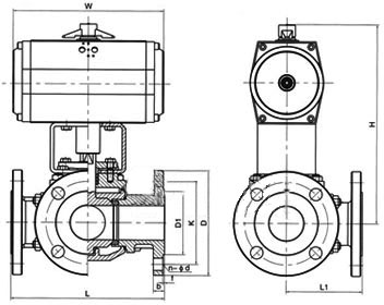
| model | Nominal diameter DN(mm) |
size(mm) | |||||||||
|---|---|---|---|---|---|---|---|---|---|---|---|
| L | L2 | D | D1 | D2 | b | f | Z-d | H | W | ||
|
Q644F-16 Ltype |
15 | 150 | 72 | 95 | 65 | 45 | 14 | 2 | 4-14 | 95 | 130 |
| 20 | 160 | 80 | 105 | 75 | 55 | 14 | 2 | 4-14 | 110 | 130 | |
| 25 | 180 | 90 | 115 | 85 | 65 | 14 | 2 | 4-18 | 120 | 140 | |
| 32 | 200 | 100 | 135 | 100 | 78 | 16 | 2 | 4-18 | 144 | 180 | |
| 40 | 220 | 110 | 145 | 110 | 85 | 16 | 3 | 4-18 | 152 | 220 | |
| 50 | 240 | 120 | 160 | 125 | 100 | 16 | 3 | 4-23 | 182 | 220 | |
| 65 | 260 | 130 | 180 | 145 | 120 | 16 | 3 | 4-18 | 193 | 240 | |
| 80 | 280 | 140 | 195 | 160 | 135 | 20 | 3 | 8-18 | 217 | 270 | |
| 100 | 320 | 160 | 215 | 180 | 155 | 20 | 3 | 8-18 | 245 | 350 | |
| 125 | 380 | 190 | 245 | 210 | 185 | 22 | 3 | 8-18 | 282 | 500 | |
| 150 | 440 | 220 | 280 | 240 | 210 | 24 | 3 | 8-23 | 319 | 600 | |
| 200 | 550 | 260 | 335 | 295 | 265 | 26 | 3 | 12-23 | 380 | 1000 | |
| 250 | 670 | 310 | 405 | 355 | 320 | 30 | 3 | 12-25 | 460 | 1400 | |
| 300 | 720 | 370 | 460 | 410 | 375 | 30 | 3 | 12-25 | 520 | 1800 | |
| model | Nominal diameter DN(mm) |
size(mm) | |||||||||
|---|---|---|---|---|---|---|---|---|---|---|---|
| L | L2 | D | D1 | D2 | b | f | Z-d | H | W | ||
|
Q645F-16 Ttype |
15 | 150 | 72 | 95 | 65 | 45 | 14 | 2 | 4-14 | 95 | 130 |
| 20 | 160 | 80 | 105 | 75 | 55 | 14 | 2 | 4-14 | 110 | 130 | |
| 25 | 180 | 90 | 115 | 85 | 65 | 14 | 2 | 4-18 | 120 | 140 | |
| 32 | 200 | 100 | 135 | 100 | 78 | 16 | 2 | 4-18 | 144 | 180 | |
| 40 | 220 | 110 | 145 | 110 | 85 | 16 | 3 | 4-18 | 152 | 220 | |
| 50 | 240 | 120 | 160 | 125 | 100 | 16 | 3 | 4-23 | 182 | 240 | |
| 65 | 260 | 130 | 180 | 145 | 120 | 16 | 3 | 4-18 | 193 | 270 | |
| 80 | 280 | 140 | 195 | 160 | 135 | 20 | 3 | 8-18 | 217 | 350 | |
| 100 | 320 | 160 | 215 | 180 | 155 | 20 | 3 | 8-18 | 245 | 500 | |
| 125 | 380 | 190 | 245 | 210 | 185 | 22 | 3 | 8-18 | 282 | 600 | |
| 150 | 440 | 220 | 280 | 240 | 210 | 24 | 3 | 8-23 | 319 | 1000 | |
| 200 | 550 | 260 | 335 | 295 | 265 | 26 | 3 | 12-23 | 380 | 1300 | |
| 250 | 670 | 310 | 405 | 355 | 320 | 30 | 3 | 12-25 | 460 | 1700 | |
| 300 | 720 | 370 | 460 | 410 | 375 | 30 | 3 | 12-25 | 520 | 2100 | |
Preparation before installation of pneumatic ball valve:
1. Ensure that the installation position of the pneumatic pipeline ball valve is in the coaxial position, and the two flanges on the pipeline shall be kept parallel to confirm that the pipeline can bear the weight of the pneumatic pipeline ball valve. If it is found that the pipeline can not bear the weight of the pneumatic pipeline ball valve, the corresponding support shall be provided for the pipeline before installation.
2. To confirm whether there are impurities and welding slag in the pipeline, the pipeline must be blown clean.
3. Check the name plate of the pneumatic pipeline ball valve, and operate the pneumatic pipeline ball valve fully open and closed for several times to confirm that the valve can work normally, and then check all details of the valve once again to ensure that the valve is intact.
4. Remove the protective covers at both ends of the valve, check whether the valve body is clean, and clean the inner cavity of the valve body. Since the sealing surface of the ball valve in the pneumatic pipeline is ball shaped, even small impurities may cause damage to the sealing surface.
Installation of pneumatic pipeline ball valve:
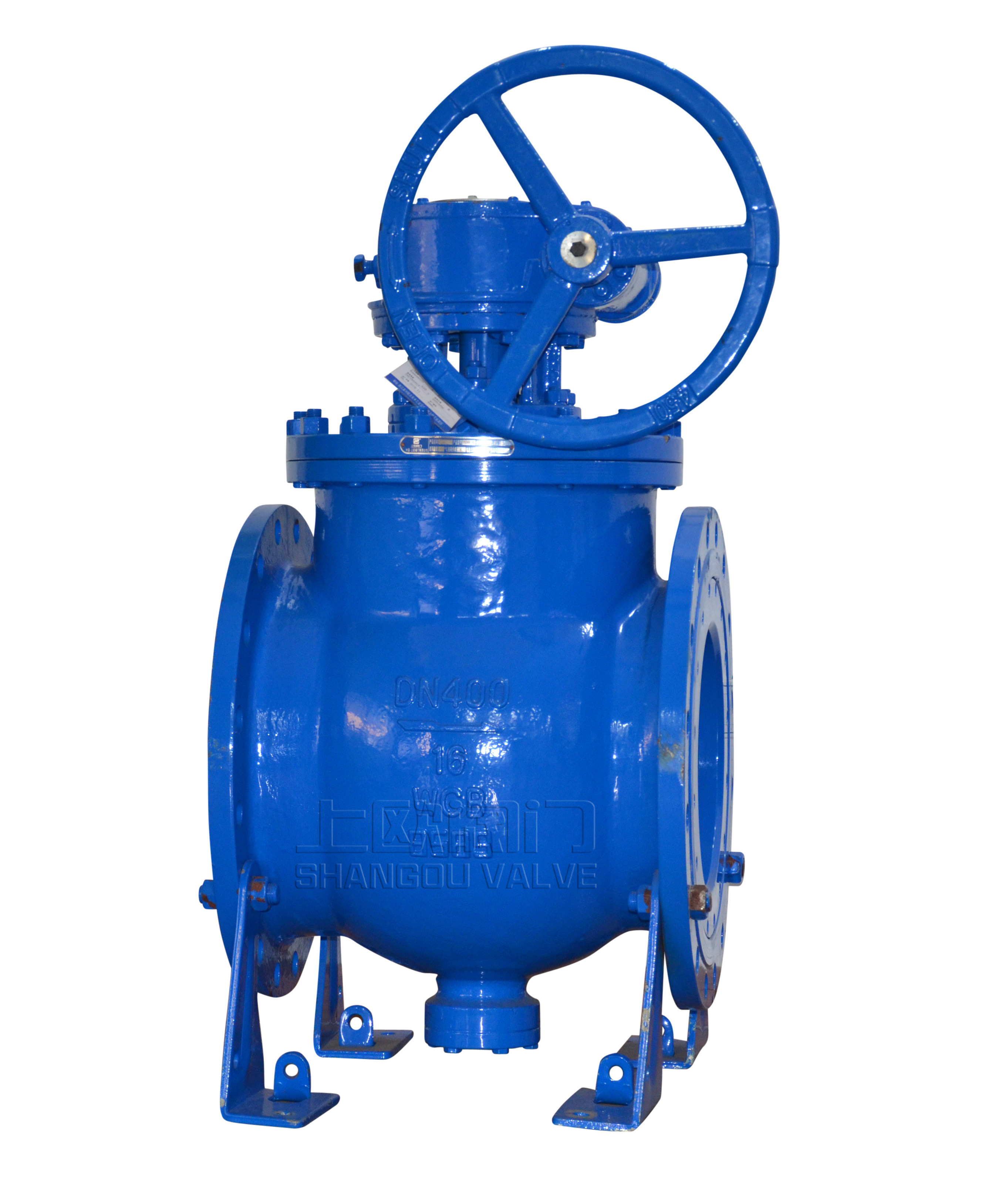
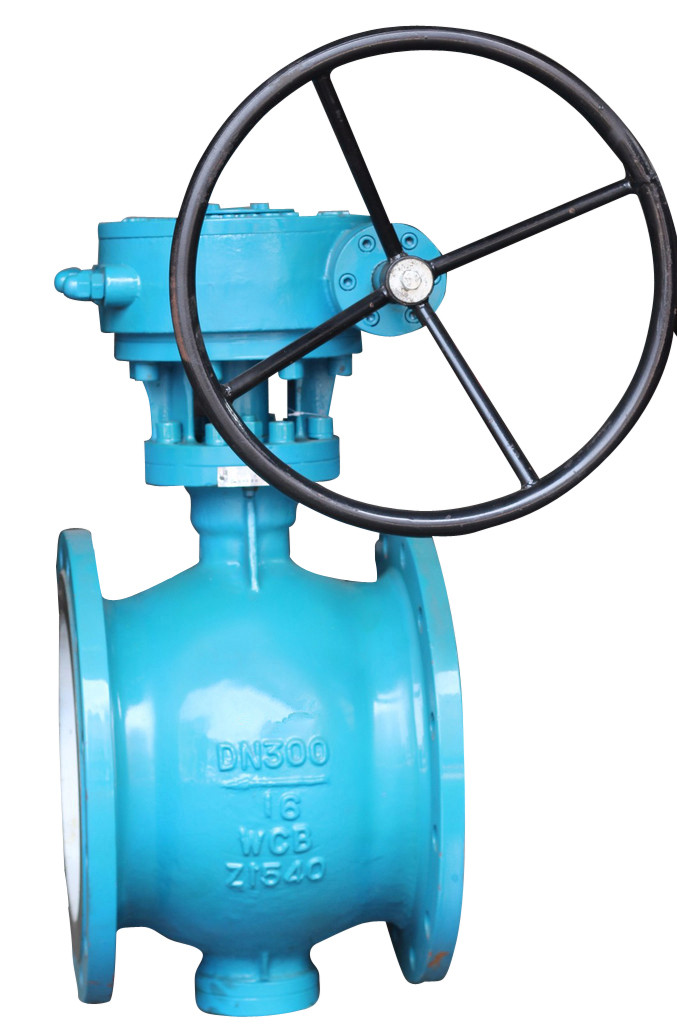
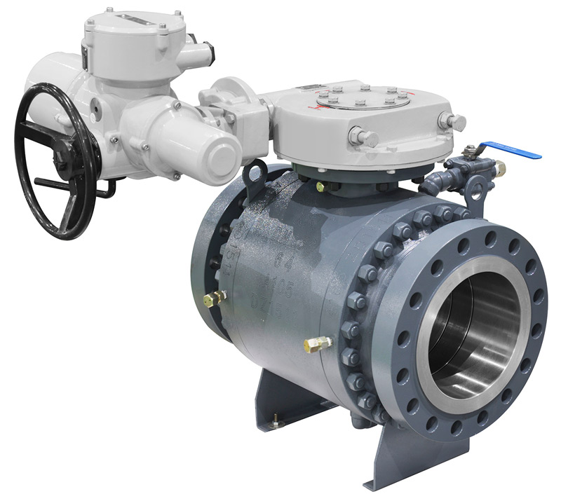
1. Any section of the pneumatic pipeline ball valve can be installed at the upstream end, and the handle pneumatic pipeline ball valve can be installed at any position of the pipeline. If the pneumatic pipeline ball valve with actuator (such as gearbox and electro pneumatic actuator) is equipped, it must be vertically installed, and the inlet and outlet of the valve shall be in horizontal position.
2. The sealing gasket shall be installed between the flange of the ball valve and the flange of the pipeline according to the design requirements of the pipeline.
3. The bolts on the flange shall be tightened symmetrically, successively and evenly.
4. If pneumatic and electric actuators are adopted for pneumatic pipeline ball valve, the installation of air source and power supply shall be completed according to the manual.
Inspection after installation of pneumatic pipeline ball valve:
1. After the installation, start the pneumatic pipeline ball valve to open and close several times. The action should be flexible and the force should be uniform. The pneumatic pipeline ball valve should work normally.
2. According to the design requirements of the pipeline pressure, the sealing performance of the joint surface between the pneumatic pipeline ball valve and the pipe flange is tested after pressurization.
常用阀门材料允许使用压力明细介绍
常用阀门材料允许使用压力明细说明。常用阀门材质国家标准代号分类
常用阀门材质国家标准代号分类有那些,上欧为您做准确说明,请参.....What is the name.....
The name of the organization t.....Main technical r.....
The main technical requirement.....Bill of material.....
1: Screw plug: Bronze / stainl.....Set up a new ben.....
Full flow streamline design, t.....General technica.....
The adjustment of piston type .....Fast Navigation
Product Line
Recommended Products
Technical Support
Copyright:Shangou Valve Co.,Ltd Record No:; Sitemap
Friendship Links: SenAu Product website