Telephone:
0577-67975099
 Location:Home > Product Center > control valve > Bfdg pipe force control valve
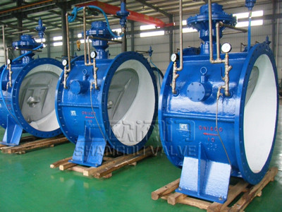
Bfdg pipe force control valve is the third generation of new butterfly multi-function pump control valve after the old manual control valve, hydraulic control butterfly valve and hydraulic control valve. The valve adopts advanced fluid design, with low energy consumption, stable operation and good sealing effect. It has the functions of electric gate valve, electric butterfly valve and check valve. Its quick closing speed and adjustable pressure relief time can effectively eliminate the harm of water hammer and protect the safety of water pump and pipe network system. The valve is suitable for the outlet pipe of centrifugal pump, mixed flow pump and axial flow pump in automatic water supply and drainage pump station. Two control devices, diaphragm type and piston type, are designed, which can be respectively applied to clean water, raw water medium, sewage and slurry water medium. In terms of product types, five specifications are developed, including common type, low-pressure backwater type and sewage type, to meet the requirements of different working conditions.
Pipe force control valve is a new pump outlet control valve developed by our company. It is the third generation of new butterfly type multi-function pump control valve after the old manual control valve, hydraulic control butterfly valve and hydraulic control valve. The valve adopts advanced fluid design, with low energy consumption, stable operation and good sealing effect. It has the functions of electric gate valve, electric butterfly valve and check valve. Its quick closing speed and adjustable pressure relief time can effectively eliminate the harm of water hammer and protect the safety of water pump and pipe network system. The valve is suitable for the outlet pipe of centrifugal pump, mixed flow pump and axial flow pump in automatic water supply and drainage pump station. Two control devices, diaphragm type and piston type, are designed, which can be respectively applied to clean water, raw water medium, sewage and slurry water medium. In terms of product types, five specifications are developed, including common type, low-pressure backwater type and sewage type, to meet the requirements of different working conditions.
The valve is compact in structure, small in size and light in weight. It is especially suitable for large diameter pipe network system. It can be widely used in power, environmental protection, metallurgy, petrochemical, water department, municipal, food and other industries, water supply and drainage system, sewage pump station, chemical fluid and other transportation systems.
1. Valve opening: the initial state is shown in (1). When the water pump is started, the water pressure enters the lower chamber of the control chamber through the bypass pipe with micro hole check valve at the inlet. The large valve plate is slowly opened together with the small valve plate under the hydraulic action of the inlet end, as shown in Fig. (2). The opening speed of the valve can be adjusted according to the working conditions to achieve the best effect.
2. Valve closing: at the moment of pump stop, the flow and pressure at the valve inlet suddenly decrease, the large valve plate closes quickly under the action of gravity (before contacting with the sealing surface, there is a buffer protection device) to cut off most of the water flow, and the small valve plate remains open under the action of the control rod to discharge the backflow At the same time, a part of the return water flows into the upper chamber of the control chamber through the bypass pipe. It is presumed that the control rod goes down, and the small valve plate is closed until the medium is completely cut off, as shown in figure (4). The valve closing time can be adjusted by the bypass valve to make the water hammer peak within the control range.

Main technical features of the product
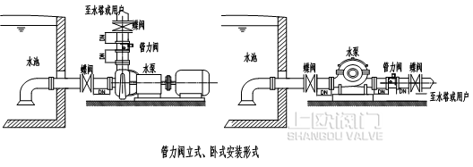
1. The pipe force valve can be installed vertically or horizontally. For the convenience of installation and maintenance, horizontal installation should be given priority when space permits, and the valve shaft should be horizontal.
2. When the valve is closed, the smooth surface of the valve plate is the inlet direction, and the side with the valve shaft and the top rod of the control cylinder is the outlet direction. Reverse installation is strictly prohibited. The distance from adjacent valves, necking and bends shall not be less than 1DN.
3. In horizontal installation, in order to improve the stress condition of pipeline, when the valve diameter is greater than 900mm, support or foundation can be set to improve the stress condition of pipeline.
| Material name | Material grade. | Main media | |
|
ANSI/AST standard |
G B |
||
| carbon steel |
WCB |
ZG25 |
Water, oil, etc |
| Ni Cr cast iron |
\ |
QT400Ni2Cr |
seawater |
| Nickel stainless steel |
CF8 (304) |
ZGlCrl8Ni9Ti ZGlCrl8Nil2Mo2Ti |
Corrosive media such as nitric acid |
| Cr Ni Mo stainless steel |
CF8M (316) |
Acetic acid corrosive medium | |
| Chromium nickel ultra low carbon stainless steel |
CF3 (304L) |
Corrosive media such as nitric acid | |
|
CF3M (316L) |
Acetic acid corrosive medium | ||
Main design and manufacturing standards
| Standard content | Standard number | Standard name |
| Enterprise standard |
Q/OPJF007-2012 |
Bfdg pipe force control valve |
|
GB/T12236 |
Butterfly Check Valve | |
|
API6D |
Butterfly check valve with damping | |
| Inspection and test standards |
GB/T13927-2008 |
Pressure test for general purpose valves |
| Flange standard |
GB9113.1-9113.4 |
Pressure test for general purpose valves |
|
GB/T12221 |
Metal valve structure length | |
| Standard of materials used |
GB/T12229 |
Technical specification of carbon steel castings for general purpose valves |
|
GB/T12230 |
Technical specification of austenitic copper castings for general purpose valves |
| project | caliber | ||
|
< 1000mm |
≥1000mm |
||
|
Valve closing time(s) |
fast |
1~2.5 |
1〜5 |
| slow |
3〜60 |
5-90 |
|
|
zuiLow working pressure(Mpa) |
=0.05 |
||
| resistance coefficient |
0.3〜1.1 |
||
| Valve opening time | |||
| Water hammer peak | S 1.5 times the rated pressure of water pump outlet | ||
| High reverse speed of water pump | S 1.2 times rated speed of water pump | ||
| Adaptive temperature | Not indicated as 0-80 ° C, can produce - 25 ° C-200 ° C | ||
| name | Common material | Chromium nickel stainless steel | Seawater resistant material |
| Valve shaft | Stainless steel 2Crl3 |
ZGlCrl8Ni9Ti |
316L |
| Diaphragm / piston | NBR / stainless steel |
EPDM/2Crl3 |
EPDM/316L |
| Sealing surface of valve body | Semi ferrite high chromium steel d507 (H) Cemented carbide STL (y) A102 stainless steel (R) |
ZGlCrl8Ni9Ti |
ZcuZn38Mn2Pb2 Manganese brass(T) |
| Hard seal pair |
D507(H)+A102(R) |
316L+316L |
T+316L |
1. Various functions: it has the functions of closure check, light load pump starting, eliminating water hammer, etc., and one valve with multiple valves can save the total investment of equipment.
2. Slowly open the pump: after starting the pump, under the action of the microporous check valve at the inlet end, the valve can only be opened after reaching a constant pressure, which can reduce the pump starting current and ensure the safety of the motor and electric control system.
3. Quick closing and slow closing: unique small valve plate structure (patent of our company 200720064765.7 "slow closing structure of small valve plate of pipe force control valve"), when stopping the pump, fast closing and then slow closing can effectively eliminate water hammer and ensure system safety.
4. Beautiful appearance: the innovative design of control device is adopted in the structure, with small external space, simple internal structure and strong operation reliability. In terms of technology, the shell and parts are precision casting, with good structural strength and simple and exquisite appearance.
5. Easy to install: butterfly valve structure, small size, light weight, small space, reduce the cost of civil engineering, can be applied to various installation methods such as surface and trench.
6. Simple maintenance:
The opening and closing of the valve is driven by the conveying medium and is automatically interlocked with the water pump without manual and external force operation;
It has no external power and components, adopts integrated structure, and has few fault points;
The hydraulic cylinder can be maintained in normal operation;
The key parts are made of high quality materials, which need no maintenance;
The filter in the external control channel has the function of self washing;
7. Energy saving and consumption reduction: the opening and closing parts are inclined butterfly plate, the water flow is smooth, and the loss along the way and local loss is very small; cancel the electro-hydraulic control system of hydraulic butterfly valve, reduce the cost, increase the reliability and stability, reduce the power consumption, and achieve the purpose of energy saving.
8. Reliable operation and sealing: it adopts the soft and hard double sealing structure (patent zl01249431.3 "valve opening and closing parts combined sealing device" patent) or metal hard sealing structure, and the friction moment of sealing pair is very small; The oblique eccentric structure seal pair shortens the valve closing stroke, reduces the slip distance of the seal ring, reduces the friction torque, achieves the effect of instantaneous clutch, and has the function of anti sediment and automatic pressure compensation; the optimized design of sealing angle of valve body and valve plate makes the valve open and close flexibly and reliably.
9. Strong adaptability: the products are diaphragm type and piston type, which are suitable for various working conditions and media. The special filter in the external control unit can effectively filter the impurity particles in the sewage, and ensure that the medium entering the diaphragm cavity or piston cylinder is clean liquid. The filter device has the function of self washing, and the bypass inlet end is equipped with a slag discharge device, which can manually and regularly discharge slag. The adjustable type can adjust the flow rate by manual or electric control according to the working conditions.
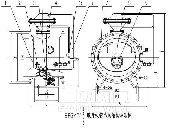
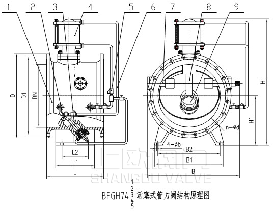
表1:
| Nominal diameter |
length |
Dimensions (reference value) |
Connection size (standard value) |
reference resources |
||||||||||||
|
0.6MPa |
1.0MPa |
|||||||||||||||
| millimeter |
L |
L1 |
L2 |
H |
H1 |
B |
B1 |
B2 |
n-b |
D |
D1 |
n-d |
D |
D1 |
n-d |
|
|
200 |
190 |
/ |
/ |
520 |
/ |
355 |
/ |
/ |
/ |
320 |
280 |
8-18 |
340 |
295 |
8-22 |
57 |
|
250 |
250 |
/ |
/ |
580 |
/ |
420 |
/ |
/ |
/ |
375 |
335 |
12-18 |
395 |
350 |
12-22 |
80 |
|
300 |
270 |
/ |
/ |
710 |
/ |
490 |
/ |
/ |
/ |
440 |
395 |
12-22 |
445 |
400 |
12-22 |
109 |
|
350 |
290 |
/ |
/ |
770 |
/ |
560 |
/ |
/ |
/ |
490 |
445 |
12-22 |
505 |
460 |
16-22 |
140 |
|
400 |
406 |
/ |
/ |
830 |
/ |
625 |
/ |
/ |
/ |
540 |
495 |
16-22 |
565 |
515 |
16-26 |
220 |
|
450 |
432 |
/ |
/ |
870 |
/ |
685 |
/ |
/ |
/ |
595 |
550 |
16-22 |
615 |
565 |
20-26 |
278 |
|
500 |
457 |
/ |
/ |
930 |
/ |
720 |
/ |
/ |
/ |
645 |
600 |
20-22 |
670 |
620 |
20-26 |
310 |
|
600 |
508 |
/ |
/ |
1090 |
/ |
910 |
/ |
/ |
/ |
755 |
705 |
20-26 |
780 |
725 |
20-30 |
451 |
|
700 |
610 |
300 |
240 |
1260 |
520 |
1050 |
760 |
650 |
4-30 |
860 |
810 |
24-26 |
895 |
840 |
24-30 |
620 |
|
800 |
660 |
360 |
220 |
1440 |
600 |
1170 |
820 |
720 |
4-30 |
975 |
920 |
24-30 |
1015 |
950 |
24-33 |
850 |
|
900 |
711 |
420 |
300 |
1535 |
650 |
1315 |
950 |
820 |
4-30 |
1075 |
1020 |
24-30 |
1115 |
1050 |
28-33 |
1060 |
|
1000 |
811 |
460 |
350 |
1750 |
700 |
1460 |
1040 |
900 |
4-36 |
1175 |
1120 |
28-30 |
1230 |
1160 |
28-36 |
1500 |
|
1200 |
850 |
500 |
410 |
1960 |
800 |
1580 |
1240 |
1070 |
4-36 |
1405 |
1340 |
32-33 |
1455 |
1380 |
32-39 |
1925 |
|
1400 |
950 |
620 |
500 |
2250 |
900 |
1900 |
1400 |
1250 |
4-36 |
1630 |
1560 |
36-36 |
1675 |
1590 |
36-42 |
2400 |
|
1600 |
1100 |
750 |
600 |
2500 |
1020 |
2100 |
1520 |
1300 |
4-36 |
1830 |
1760 |
40-36 |
1915 |
1820 |
40-48 |
3200 |
|
1800 |
1200 |
860 |
700 |
2820 |
1150 |
2400 |
1620 |
1400 |
4-36 |
2045 |
1970 |
44-39 |
2115 |
2020 |
44-48 |
4052 |
|
2000 |
1300 |
980 |
820 |
3150 |
1250 |
2750 |
1800 |
1550 |
4-48 |
2265 |
2180 |
48-42 |
2325 |
2230 |
48-48 |
5126 |
|
2200 |
1450 |
1100 |
900 |
3500 |
1360 |
3000 |
1980 |
1700 |
4-48 |
2475 |
2390 |
52-42 |
2560 |
2440 |
52-62 |
7860 |
|
2400 |
1550 |
1250 |
1100 |
3800 |
1480 |
3200 |
2320 |
2020 |
4-48 |
2685 |
2600 |
56-42 |
2760 |
2650 |
56-56 |
8928 |
|
2600 |
1700 |
1400 |
1200 |
4180 |
1600 |
3500 |
2380 |
2050 |
4-48 |
2905 |
2810 |
60-48 |
2960 |
2850 |
60-48 |
10120 |
|
2800 |
1850 |
1550 |
1350 |
4550 |
1700 |
3800 |
2520 |
2240 |
4-48 |
3115 |
3020 |
64-48 |
3180 |
3070 |
64-48 |
13100 |
|
3000 |
2000 |
1680 |
1460 |
4900 |
1850 |
4100 |
2990 |
2660 |
4-48 |
3315 |
3220 |
68-48 |
3400 |
3290 |
68-48 |
21010 |
表2:
| Nominal diameter |
length |
Dimensions (reference value) |
Connection size (standard value) |
reference resources |
||||||||||||
|
4.0MPa |
6.4MPa |
|||||||||||||||
| millimeter |
L |
L1 |
L2 |
H |
H1 |
B |
B1 |
B2 |
n-b |
D |
D1 |
n-d |
D |
D1 |
n-d |
|
|
200 |
190 |
/ |
/ |
520 |
/ |
355 |
/ |
/ |
/ |
375 |
320 |
12-30 |
415 |
345 |
12-36 |
87 |
|
250 |
250 |
/ |
/ |
580 |
/ |
420 |
/ |
/ |
/ |
450 |
385 |
12-33 |
470 |
400 |
12-36 |
110 |
|
300 |
270 |
/ |
/ |
710 |
/ |
490 |
/ |
/ |
/ |
515 |
450 |
16-33 |
530 |
460 |
16-36 |
139 |
|
350 |
290 |
/ |
/ |
770 |
/ |
560 |
/ |
/ |
/ |
580 |
510 |
16-36 |
600 |
525 |
16-39 |
190 |
|
400 |
406 |
/ |
/ |
830 |
/ |
625 |
/ |
/ |
/ |
660 |
585 |
16-39 |
670 |
585 |
16-42 |
290 |
|
450 |
432 |
/ |
/ |
870 |
/ |
685 |
/ |
/ |
/ |
685 |
610 |
20-39 |
/ |
/ |
/ |
368 |
|
500 |
457 |
/ |
/ |
930 |
/ |
720 |
/ |
/ |
/ |
755 |
670 |
20-42 |
/ |
/ |
/ |
410 |
|
600 |
508 |
/ |
/ |
1090 |
/ |
910 |
/ |
/ |
/ |
890 |
795 |
20-48 |
/ |
/ |
/ |
561 |
|
700 |
610 |
300 |
240 |
1260 |
520 |
1050 |
760 |
650 |
4-30 |
995 |
900 |
24-48 |
/ |
/ |
/ |
740 |
|
800 |
660 |
360 |
220 |
1440 |
600 |
1170 |
820 |
720 |
4-30 |
1140 |
1030 |
24-56 |
/ |
/ |
/ |
980 |
|
900 |
711 |
420 |
300 |
1535 |
650 |
1315 |
950 |
820 |
4-30 |
1250 |
1140 |
28-56 |
/ |
/ |
/ |
1210 |
|
1000 |
811 |
460 |
350 |
1750 |
700 |
1460 |
1040 |
900 |
4-36 |
1360 |
1250 |
28-56 |
/ |
/ |
/ |
1730 |
Table 3
Note: for other pressure levels, please consult the technical department of the company. Different connection standards can be designed and produced according to user requirements.
Due to product improvement, there may be differences between the material object and the publicity materials. The company reserves the right to interpret the above data. Please contact the company's technical department when ordering specific parameters.
自动水力控制阀进出口压力推荐及防.....
Maintenance Manu.....
V-type ball valve is a kind of.....蝶阀常见的试验和安装及故障排除方.....
1、本产品无论是手动、气动、液动、电动各部件在出厂前均经严.....管力阀八大技术特点分析
管力阀八大技术特点分析旋球阀产品概述
旋球阀结合球阀的优越密 封性能与蝶阀的优势结构性能研发而成,.....常用球阀等产品所执行的国家标准解.....
《通用阀门法兰和对焊连接钢制球阀》GB/T12237-89 .....管力阀是一种什么样的阀门
管力阀是我公司历时五年研发的zui新水泵出口控制阀,是继老.....调流调压阀焊接技术要求
调流调压阀是一种多功能活塞式调节阀、该产品有活塞式、套筒式、.....Fast Navigation
Product Line
Recommended Products
Technical Support
Copyright:Shangou Valve Co.,Ltd Record No:; Sitemap
Friendship Links: SenAu Product website