0577-67975099
 QQ
QQ WeChat
 邮箱
邮箱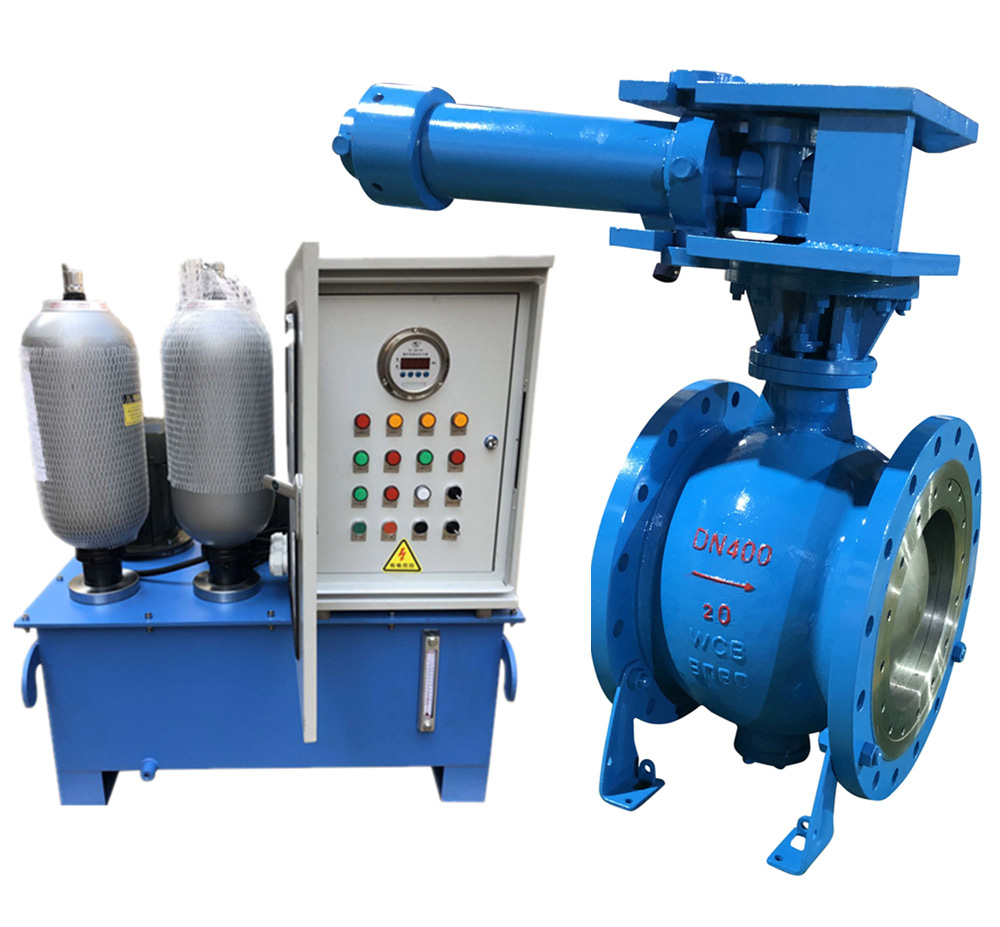
Telephone:
0577-67975099
 Location:Home > Product Center > Air Valve > Hydraulic control hydraulic ball valve
 Telephone:
0577-67975099
Telephone:
0577-67975099
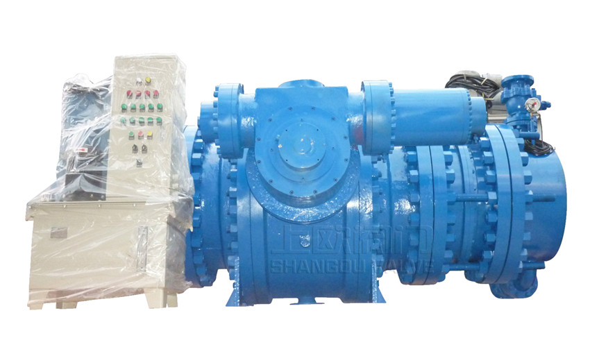

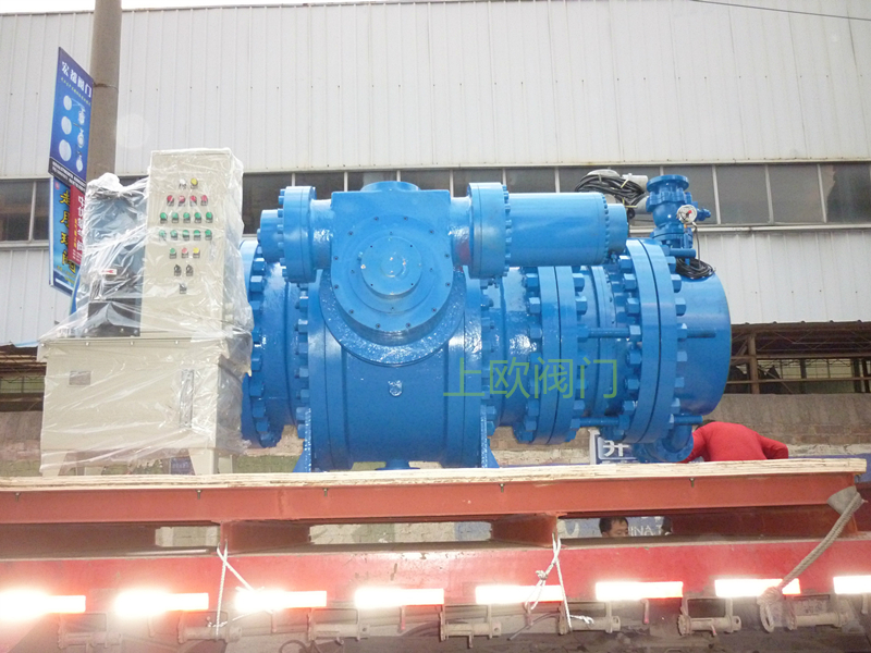
The hydraulic control ball valve of hydraulic turbine inlet is mainly used in large and medium-sized hydropower stations. It is installed in front of hydraulic turbine and used as inlet ball valve of hydraulic turbine. The upstream is connected with the penstock and the downstream is connected with the spiral case inlet pipe.
Hydraulic control heavy hammer ball valve is a kind of valve which does not need power and relies on the potential energy of heavy hammer to automatically close the valve. It is suitable for hydraulic power generation, water lifting engineering, oil and gas transmission pipeline emergency closing due to fault, which can not play the role of pipeline cut-off. The closing is completed by fast slow two stages, which not only meets the requirements of fast closing, but also avoids the harm of water hammer caused by medium flow It has the advantages of reliable sealing performance, convenient maintenance, smaller flow resistance coefficient than other types of valves (such as gate valve, butterfly valve, etc.), less energy consumption and high efficiency; from the control mechanism, when closing the valve, it relies on the potential energy of the heavy hammer, which is more electric and hydraulic, and does not need the regular power supply. The hydraulic heavy hammer ball valve can be operated on site, and can also be connected with PLC to realize remote control, so as to realize the operation with few people or nobody The hydraulic control heavy hammer ball valve is equipped with a dual pump (electric pump + manual pump) system, which can manually open or close the ball valve without power source.
1、JB/T7745-95 2、GB/T12237-89
3、GB/T14478-93 4、GB/T13927-92
5、GB/T9113.1~12-2000 6、GB/T13402-92
7、GB/T12221-89 8、JB/T79.1~4-1994
9.Other relevant standards and foreign standards can be adopted. Flange size and size can be manufactured according to user's requirements, but it must be indicated in the order contract.
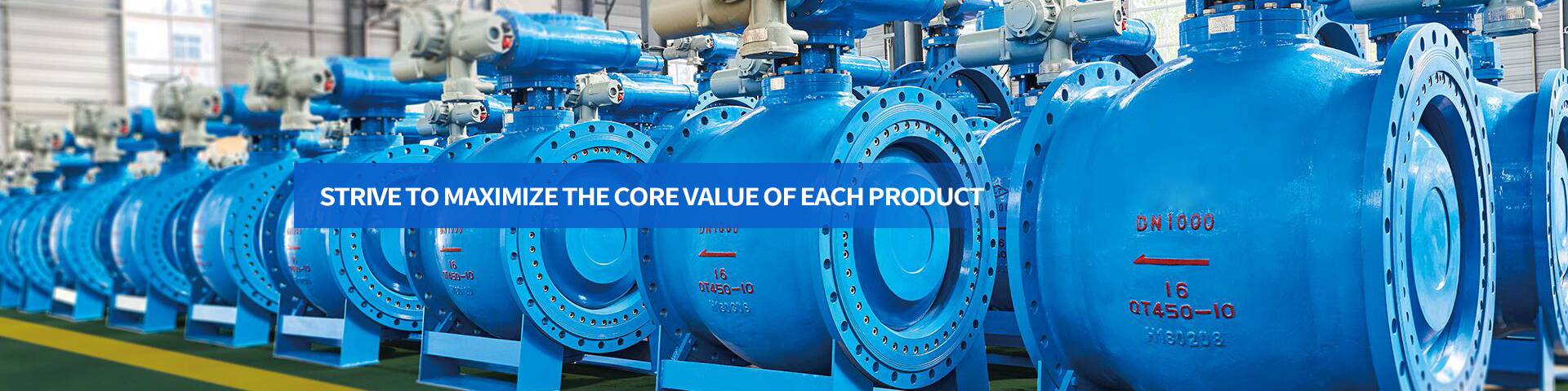
This series of valves have reasonable structure, high strength and no vibration at high flow rate. It can be opened according to the program
When starting, the flow channel is completely unblocked, and the water loss is small during operation. When the power is cut off (or powered on), it will automatically close according to the preset time and angle
It is suitable for water, sea water, oil, coal powder, coke oven gas, dust gas and other media
For start check and cut-off function in pipeline. It has the following characteristics:
1. It can replace the stop valve and check valve at the outlet of the water pump, and integrates the mechanical, electrical and hydraulic functions, and occupies a small area;
2. During the opening or closing process of the valve, the valve seat and the ball crown do not rub each other, so the service life of the valve is long;
3. The opening and closing of the valve is not affected by sludge and debris, which is applicable to the condition of slurry water;
4. The metal and non-metallic seals have good self sealing performance. The greater the water pressure, the greater the specific pressure;
5. High degree of automation, local, remote and linkage control;
6. The electrical system can adopt PLC intelligent control system or ordinary relay type system;
7. The motor power of the hydraulic system is small, the working efficiency is high, the pressure maintaining performance is good, and the oil pump starting interval is long;
8. With obvious opening indication and mechanical limit adjustment mechanism, the travel switch device is waterproof and dustproof, not exposed, stable performance
Long service life;
9. The electrical operation interface is humanized and diversified, which can be designed as ordinary button type, text type, touch screen type, or according to the needs of customers
The design of man-machine interface.
| Part name | Materials |
| Valve body |
WCB |
| Left body |
WCB |
| Spheroid |
WCB |
| Sealing pair | Stainless steel / stainless steel |
| Valve shaft | Stainless steel, carbon steel |
| sliding bearing | CSB composite |
| Flexible graphite | |
| Wall board |
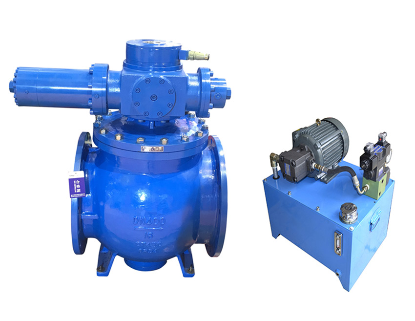
The hydraulic hydraulic ball valve is mainly used for the water containing sediment and the temperature is - 28 ~ 80 ℃. As the opening and closing device on the water pipe, it can only be fully opened and closed, and can not be used for regulation. It has the advantages of small flow resistance, flexible opening and closing, safe and reliable, and convenient operation.
The piston water stop ring structure with double sealing rings is adopted, which is divided into upstream maintenance seal and downstream working seal. The sealing rings are set at the upstream and downstream sealing positions of the annular valve core, and the piston stop ring is pushed to compress with it by the hydraulic system to realize the sealing. When the ball valve is normally closed, the downstream working seal is closed and water stops smoothly. When the downstream working seal is overhauled or replaced, the upstream maintenance seal is closed and locked by the mechanical locking device.
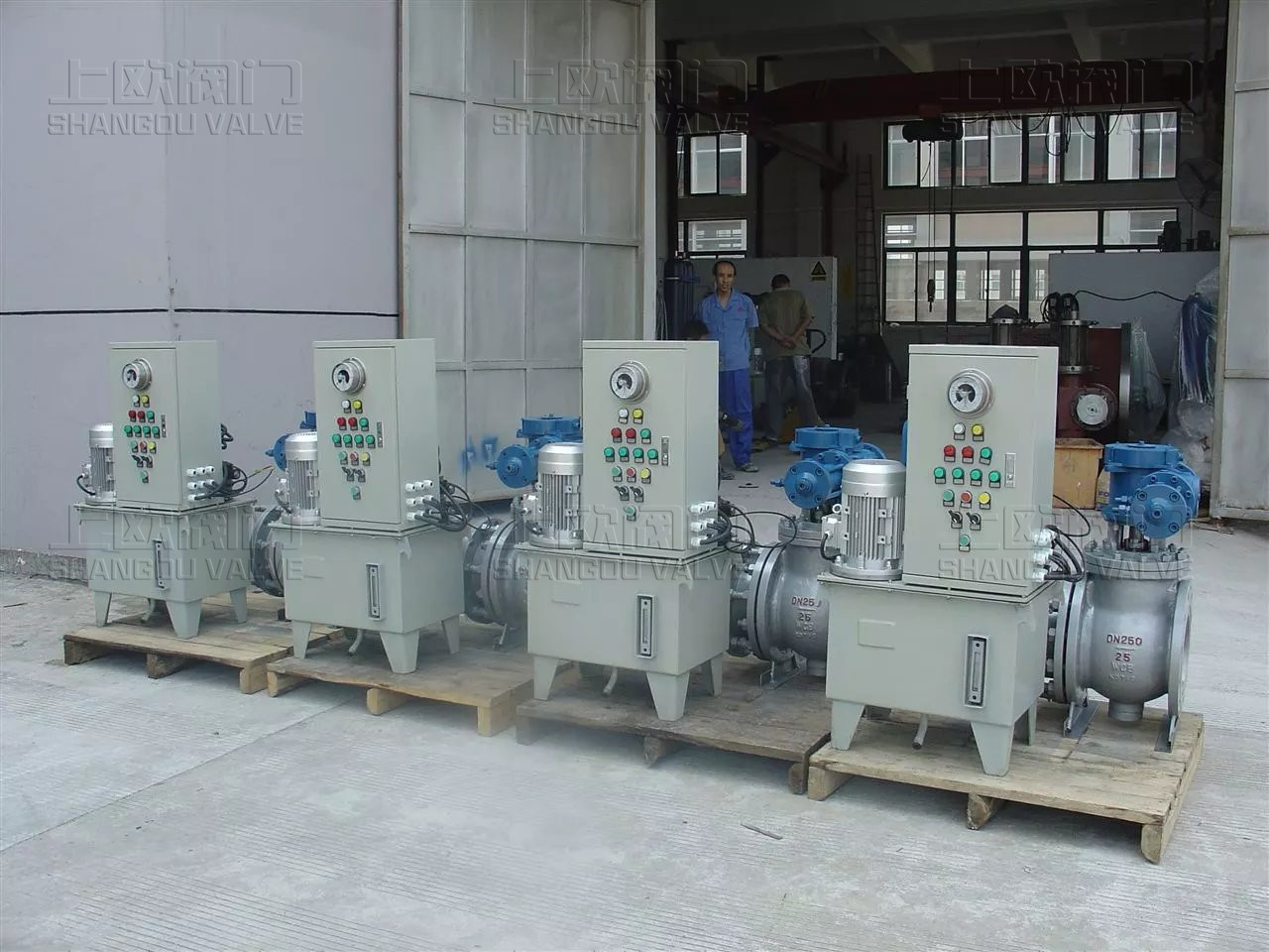
The operating mechanism is a hydraulic operating mechanism (straight cylinder servomotor), and the straight cylinder servomotor is a piston fork mechanism. It is equipped with manual locking device, main valve position signal indicating device and manual locking spindle input or output signal indicating device. The manual locking device can resist the maximum operating pressure of servomotor and avoid valve misoperation.
Position travel switches are set on the upstream and downstream sealing rings of the ball valve. After being connected to the central control room through the circuit, the state of the sealing ring can be accurately understood, so as to accurately operate the servomotor valve.
The upstream of the hydraulic ball valve (main valve) is welded with the inlet pipe through the short pipe in front of the valve, and the downstream is connected with the spiral case of the hydraulic turbine through the expansion joint, so as to facilitate the installation and maintenance of the hydraulic ball valve (main valve) and the adjustment of the expansion joint.
The hydraulic ball valve (main valve) is equipped with bypass production pipeline, which aims to balance the pressure at the upstream and downstream ends of the valve before opening the main valve, and reduce the opening and closing torque of the main valve. The bypass valve is a hydraulic ball valve, and a manual valve is set in front of the hydraulic ball valve for maintenance of the bypass hydraulic ball valve.
The DN80 wedge gate valve is set on the top of the expansion joint. When the penstock fills water to the downstream turbine, the valve is fully opened to remove the air on the water surface. Manual gate valves with dn80mm and PN4.0MPa are set at the bottom and expansion joint of the ball valve, which are used to fully remove the dirt and water in the volute and water in the valve body cavity during the maintenance of hydraulic turbine.
Two throttle valves are set at the two oil inlets of the servomotor, so that the opening and closing time of the valve can be adjusted according to customer requirements.
The hydraulic hydraulic ball valve is mainly used for the water containing sediment and the temperature is - 28 ~ 80 ℃. As the opening and closing device on the water pipe, it can only be fully opened and closed, and can not be used for regulation. It has the advantages of small flow resistance, flexible opening and closing, safe and reliable, and convenient operation.
The piston water stop ring structure with double sealing rings is adopted, which is divided into upstream maintenance seal and downstream working seal. The sealing rings are set at the upstream and downstream sealing positions of the annular valve core, and the piston stop ring is pushed to compress with it by the hydraulic system to realize the sealing. When the ball valve is normally closed, the downstream working seal is closed and water stops smoothly. When the downstream working seal is overhauled or replaced, the upstream maintenance seal is closed and locked by the mechanical locking device.
The operating mechanism is a hydraulic operating mechanism (straight cylinder servomotor), and the straight cylinder servomotor is a piston fork mechanism. It is equipped with manual locking device, main valve position signal indicating device and manual locking spindle input or output signal indicating device. The manual locking device can resist the maximum operating pressure of servomotor and avoid valve misoperation.
Position travel switches are set on the upstream and downstream sealing rings of the ball valve. After being connected to the central control room through the circuit, the state of the sealing ring can be accurately understood, so as to accurately operate the servomotor valve.
The upstream of the hydraulic ball valve (main valve) is welded with the inlet pipe through the short pipe in front of the valve, and the downstream is connected with the spiral case of the hydraulic turbine through the expansion joint, so as to facilitate the installation and maintenance of the hydraulic ball valve (main valve) and the adjustment of the expansion joint.
The hydraulic ball valve (main valve) is equipped with bypass production pipeline, which aims to balance the pressure at the upstream and downstream ends of the valve before opening the main valve, and reduce the opening and closing torque of the main valve. The bypass valve is a hydraulic ball valve, and a manual valve is set in front of the hydraulic ball valve for maintenance of the bypass hydraulic ball valve.
The DN80 wedge gate valve is set on the top of the expansion joint. When the penstock fills water to the downstream turbine, the valve is fully opened to remove the air on the water surface. Manual gate valves with dn80mm and PN4.0MPa are set at the bottom and expansion joint of the ball valve, which are used to fully remove the dirt and water in the volute and water in the valve body cavity during the maintenance of hydraulic turbine.
Two throttle valves are set at the two oil inlets of the servomotor, so that the opening and closing time of the valve can be adjusted according to customer requirements.
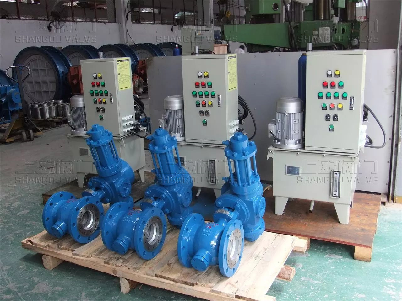
The overall dimensions and specific technical parameters of the product are designed according to different requirements. The specific data can be contacted with the technical department of our factory. The hydraulic station includes oil pump unit, manual pump, accumulator, solenoid valve, overflow valve, flow control valve, stop valve, hydraulic manifold block, oil tank and other parts. Manual pump is used for system debugging and valve opening and closing under special working conditions.
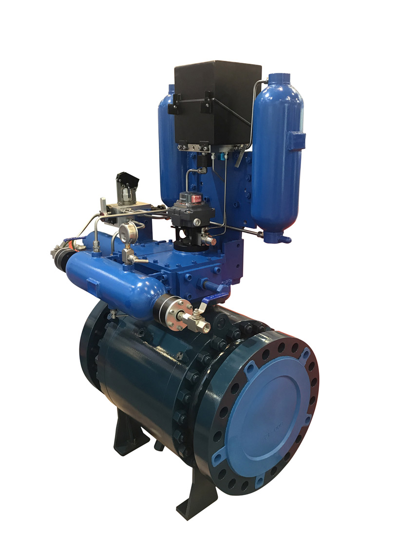
In the accumulator type system, the accumulator provides the active power source for the valve opening and closing. In the accumulator type system, two accumulators are standby for each other and provide active power source for valve closing.

The control characteristics of electromagnetic directional valve in hydraulic system are generally positive action type, that is, the solenoid valve is powered on, the ball valve is opened and the electric ball valve is closed; otherwise, it is the reaction type, that is, the solenoid valve loses power and the ball valve is closed. The conventional matching electromagnetic directional valve is positive action type, and the reaction type shall be specified when ordering.
Hydraulic hydraulic ball valve is divided into soft seal ball valve and hard seal ball valve. The soft seal ball valve is mainly suitable for the power station with clean water quality, no sediment, quartz and other impurities; the sealing is reliable, and there will be no leakage after cutting off the water flow. Hard seal water and electricity ball valve: it is mainly suitable for the power station with clean water quality, no sediment, quartz and other impurities; it has a long service life. Hard seal hydropower
The ball valve adopts the structure of metal hard surface seal and piston type seal ring with double-sided water stop, which is divided into upstream maintenance seal and downstream working seal; stainless steel sealing ball crown is set at the upstream and downstream sealing positions of the ball; when the main valve is closed, the sealing ring is pressed with the ball crown under the action of the hydraulic system to realize sealing; when the main valve is opened, the sealing ring is pushed to leave under the action of the hydraulic system Ball crown, open, no friction. When the ball valve is closed normally, the downstream working sealing ring is closed and the water stops smoothly. When the downstream unit is overhauled or the downstream working seal is replaced, the upstream maintenance seal ball is closed and locked by mechanical locking device.
The operating mechanism of ball valve is hydraulic operating mechanism (straight cylinder servomotor), and the main valve is equipped with valve switch position indication device; the ball valve is equipped with opening and closing position signal device, which is connected with the control cabinet and central control room; the valve is opened and closed so as to accurately operate the switch valve of the power connector; it can more accurately understand the switch state of the main valve and accurately control and operate The main valve opens and closes.
The upstream of the hydraulic ball valve (main valve) is welded with the inlet pipe through the short pipe in front of the valve, and the downstream is connected with the turbine volute through adjusting the expansion joint, so as to facilitate the installation and maintenance of the hydraulic ball valve (main valve). The expansion joint adjustment range of the hydraulic ball valve (main valve) is 0 ~ 50 mm, and the electric ball valve (secondary valve can also be manually) is set in the bypass pipe. Its purpose is to balance the pressure at the upstream and downstream ends of the valve and reduce the opening and closing force of the main valve Moment. The control system and opening and closing signals of the electric ball valve are directly connected to the central control room.
Position travel switches are set on the upstream and downstream sealing rings of the main valve, which are connected to the central control room through the circuit, so as to accurately understand the status of the upstream and downstream sealing rings and the opening and closing of the main valve.
A wedge gate valve of DN 100 is set in the short section, which is fully opened when the penstock fills water to the downstream turbine; and it is closed when the downstream unit is overhauled or the downstream working seal is replaced, so as to facilitate the downstream maintenance.
At the bottom of the ball valve, a manual gate valve of DN 100 mm and PN 2.5 MPa is set to fully remove the dirt in the valve body cavity and the water in the volute when repairing the turbine.
Two throttle valves are set at the two oil inlets of the servomotor, so that the opening and closing time of the valve can be adjusted according to customer requirements.
常用阀门材料允许使用压力明细介绍
常用阀门材料允许使用压力明细说明。常用阀门材质国家标准代号分类
常用阀门材质国家标准代号分类有那些,上欧为您做准确说明,请参.....What is the name.....
The name of the organization t.....Main technical r.....
The main technical requirement.....Bill of material.....
1: Screw plug: Bronze / stainl.....Set up a new ben.....
Full flow streamline design, t.....General technica.....
The adjustment of piston type .....Fast Navigation
Product Line
Recommended Products
Technical Support
Copyright:Shangou Valve Co.,Ltd Record No:; Sitemap
Friendship Links: SenAu Product website