0577-67975099
 QQ
QQ WeChat
 邮箱
邮箱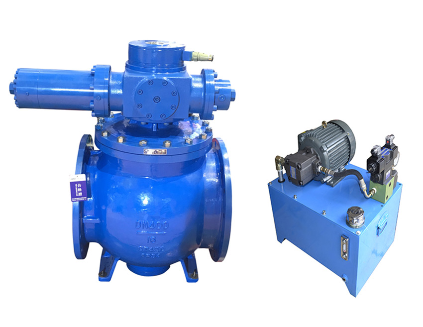
Telephone:
0577-67975099
 Location:Home > Product Center > Air Valve > Hydraulic control check eccentric hemisphere valve
 Telephone:
0577-67975099
Telephone:
0577-67975099
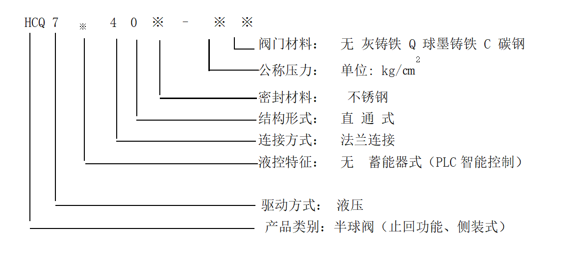
Hydraulic check eccentric hemispherical valve is an advanced pipeline control equipment at home and abroad. It is mainly installed at the pump outlet of various pumping stations such as water conservancy, electric power, water supply and drainage to replace the function of check valve and gate valve. < / BR > Product Name: hydraulic check eccentric hemisphere valve Nominal diameter: DN80 ~ DN2000 Nominal pressure: pn2.5 ~ pn64 Applicable media: sediment water, sea water, reservoir water, oil, etc Medium temperature: ≤ 80 ℃ Valve opening time: 3 ~ 120s (adjustable) Valve closing time: 3 ~ 120s (adjustable)
Hydraulic check eccentric hemispherical valve is an advanced pipeline control equipment at home and abroad. It is mainly installed at the pump outlet of various pumping stations such as water conservancy, electric power, water supply and drainage to replace the function of check valve and gate valve. When working, the valve cooperates with the pipeline host, according to the hydraulic transition process principle, through the preset opening and closing procedures, effectively eliminates the pipeline water hammer, realizes the reliable cut-off of the pipeline, and plays a role in protecting the safety of the pipeline system.
The hydraulic check eccentric hemisphere valve produced by our company has high degree of automation, complete functions, stable and reliable performance. It is a new generation of intelligent, efficient and energy-saving products developed by our company's designers on the basis of extensive collection, research and summary of the performance of similar products at home and abroad, and the introduction of a number of research results in valve, hydraulic, electrical and other industries. The company has strong technical force, and can develop and design independently according to the special requirements of users to meet the needs of the majority of users for such products. According to the structure of hemispherical valve, it can be divided into top mounted eccentric hemisphere valve and side mounted eccentric hemisphere valve.
The main features of the product are as follows:
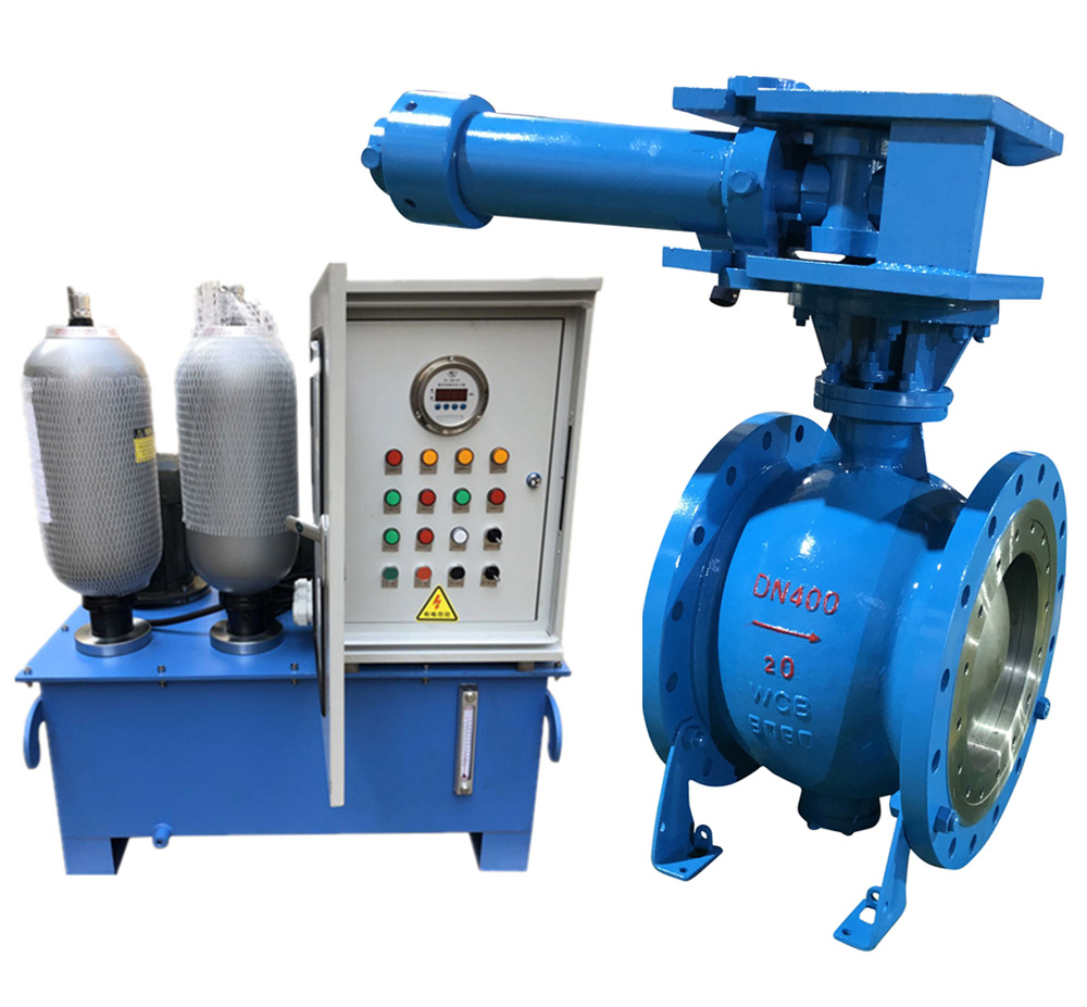
1. It can replace the original electric gate valve and check valve at the water pump outlet, and integrate the mechanical, electrical and hydraulic systems into a whole, so as to reduce the floor space and infrastructure investment.
2. The electro-hydraulic control function is complete, without additional configuration, it can be used as a stand-alone system for local debugging and control; it can also be used as a device unit of DCS through I / O The channel is centrally managed by the central computer to realize linkage operation with water pump and other pipeline equipment; it is also equipped with manual function, which can be opened and closed manually when there is no power supply, so as to meet the valve commissioning and control requirements under special working conditions.
3. It has good controllability, wide adjustment range and strong adaptability. The electro-hydraulic control system is equipped with multiple adjusting nodes, which can be set for opening and closing procedures according to different pipeline control requirements. When the conditions for opening and closing the valve are met, the valve can be opened automatically according to the preset time and angle, and divided into two stages of fast closing and slow closing. It can effectively eliminate destructive water hammer, prevent pump runaway accident, reduce the pressure fluctuation of pipe network system, and ensure the safe and reliable operation of equipment.
4. Straight through type, side mounted structure, without blocking the passage through, will not appear ash or stuck phenomenon. The switch is light, the ball is separated from the shell when opening, without any contact, small starting torque and flexible rotation. When closing, the squeeze cutting effect of hemisphere and valve seat can remove the dirt on the sealing surface, and the sealing is tight and reliable. The eccentric structure of the sealing surface enables the spherical surface to automatically compensate for wear and maintain the sealing of the valve with long service life.
| Part name | Material Science | Part name | Material Science |
| Valve body | Ductile iron, carbon steel | Sealing surface | stainless steel |
| Eccentric ball | sliding bearing | Copper alloy, CSB | |
| Stainless steel, stainless iron | Filler | Flexible graphite | |
| Valve seat | Stainless steel, PTFE | Executive Agency | carbon steel |
The valve electrical control system is divided into ordinary type and PLC intelligent control type according to the main logic element category. The factory matching is general type, and PLC intelligent control type should be explained when ordering. Each type is divided into the following main working conditions:
Operating conditions of open valve centrifugal pump (including centrifugal mixed flow pump): start the pump first, and then open the valve after delaying the predetermined time, or the pump valve is opened at the same time.
Operating conditions of open valve axial flow pump (including axial-flow mixed flow pump): the pump valve is opened at the same time, or the valve is opened to a certain angle before starting the pump.
The electric control system of the valve is equipped with local control circuit and remote linkage control circuit. The local control circuit is mainly used for on-site debugging, and the remote linkage control circuit is generally used in normal operation.
The power supply of oil pump motor is AC380V, and the control uninterruptible power supply is dc220v or other power levels AC220V, dc110v, etc.
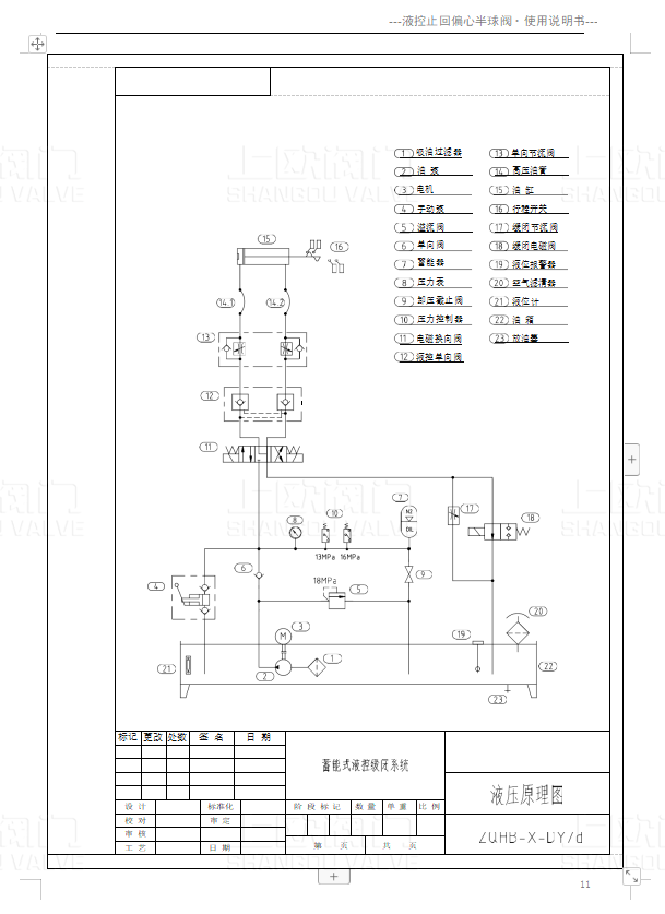
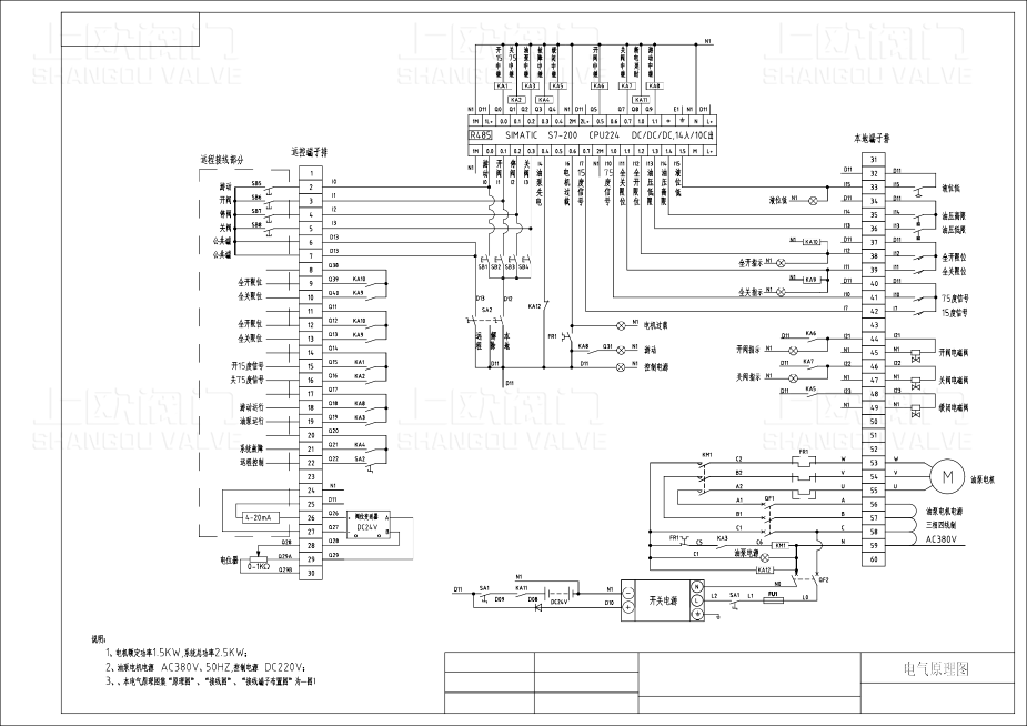
The hydraulic control principle is detailed in (Annex 3), and the electrical control principle is shown in (Annex 4).
Automatic pressure holding
Close the air switch, turn on the power supply AC380V of the oil pump, and the power indicator is on;
When the change-over switch is turned to the "on" position of the control power supply, the automatic pressure maintaining unit of the control system will start automatically, and the oil pump will automatically start to charge the system. When the pressure increases to the high-end set point of pressure relay (16MPa), the oil pump stops. In the future, the pressure maintaining function will be effective no matter in "local" or "remote", "open valve" or "close valve" state. That is, when the system pressure drops to the low set point (13Mpa) of the pressure relay, the oil pump will automatically start charging and stop at the high pressure set point.
The energy stored in the accumulator is enough to open or close the valve in the whole process once when AC380V power supply fails and the oil pump cannot be started.
Turn the transfer switch to the "release" position to release the automatic pressure holding function.
Local control
Turn the transfer switch to the "local" position.
Valve opening: press the valve opening button on the local control box, and the valve opening indicator light will be on, then the valve will open at the set speed until the full open position (full open indicator light is on) will automatically stop the valve opening action, and the valve opening indicator light will automatically turn off.
The valve opening time can be adjusted by rotating the flow of the flow control valve (one-way throttle valve on the manifold block). Different valve opening times can be achieved to adapt to the actual working conditions. The time adjustment range is shown in the table above.
Valve closing: press the valve closing button and the valve closing indicator light will be on, then the valve will close the valve at the set speed until the fully closed position (full close indicator light is on) and the valve closing indicator light will be off automatically. The valve closing is divided into two stages: fast closing and slow closing, and the rotary closing flow control valve is adjusted
(one-way throttle valve on the manifold block) and slow closing throttle valve are respectively realized. The adjustment range is shown in the table above.
Stop: in the process of opening and closing the valve, press the stop button to stop the valve at any intermediate position.
Remote control
Turn the transfer switch to the "remote" position.
Valve opening:
Start the pump first and then open the valve
When the water pump is started in the central control room, the normally open contact of the water pump control relay is closed after a predetermined time delay, and the valve automatically opens and maintains pressure according to the predetermined procedure. If the delay time is set to zero, the pump valve can be started at the same time.
Open the valve first and then start the pump
Press the remote valve opening button, the oil pump starts and the valve opens. When the valve is opened to a certain angle (15 degrees), the pump start stroke switch is pressed and the signal is sent out, and the water pump is started in the central control room. At the same time, the open valve button sends out the pump start signal, which can also realize the pump valve start at the same time.
Valve closing:
The pump valve is normally closed at the same time
When the water pump stops, the solenoid valve is powered on for reversing, and the valve is closed according to the predetermined procedure.
Close the valve first and then stop the pump
Press the remote valve closing button to close the valve; when the valve is closed to a certain angle (75 degrees), the travel switch is pressed to send a signal, and the remote control room stops the water pump.
Linkage power loss protection:
The electric control equipment is connected with DC24 V standby power supply. When the conventional power supply loses power, the standby power supply is automatically connected to ensure that the valve is closed after power failure.
Remote monitoring
In addition to receiving remote valve opening, closing, stopping and pump status signals, the control system also outputs various status signals for remote DCS monitoring, mainly including valve position signal (0 °, 15 °, 75 ° and 90 °), remote status signal, oil pump status signal, fault signal, valve position 4 ~ 20mA analog signal, etc., and the signals are passive dry contact switching signal.
Manual operation
When the power supply loses power, the valve can be opened and closed by shaking the manual pump.
The manual function is mainly used for valve debugging with standby power supply, or for valve emergency closing under special circumstances.
When there is no electricity or manual operation is needed, the solenoid valve core is pushed manually to make the oil circuit in the corresponding state. The manual operation of the valve can be realized by shaking the manual oil pump.
Adjustment method for high and low points of pressure relay:
Look at the hydraulic schematic diagram and find the pressure relay. Turn the adjusting screw at the tail of the pressure relay with an internal hexagonal wrench. Turn it to the left, and the adjusted pressure will decrease. Turn it to the right, and the adjusted pressure will increase. (it has been adjusted before delivery, and it is forbidden to adjust without permission)
Lifting
It is not allowed to turn over or put upside down during transportation and lifting; after unpacking, crane shall be used for lifting, and the balance position shall be selected among the four lifting points.
Storage
When the product is stored for a long time, it should be placed in a dry place, the inlet and outlet ends should be sealed, and the sealing surface should be coated with antirust oil. During temporary parking, auxiliary support can be added at the position of actuator to keep stable. If it is not installed for half a year, the hydraulic system needs to be cleaned and replaced.
The valve is not allowed to be stored in the open air.install
Before installation, it is necessary to check whether the parameters of the valve name plate meet the use requirements; clean the valve body channel and ball, and check
Whether the parts are damaged and whether the connecting bolts of all parts are tight.
When installing the valve, please confirm the relative orientation of the hydraulic transmission system and the water pump outlet pipe, and install the valve at the water pump outlet.
Note: the arrow direction on the valve body is "sealing pressure bearing direction". When it is installed at the water pump outlet, the arrow points to water
pump
The hemispherical valve installed on the foundation should be leveled to ensure that the valve shaft does not tilt. The auxiliary support of the valve is mainly used to ensure the smooth installation and operation of the valve, and should not bear a large amount of axial water thrust of the pipeline perpendicular to it; the axial water thrust should be transmitted to the bearing foundation through the pipeline in front of the valve or the pipeline behind the valve.
1. When leaving the factory, each part has been adjusted and set according to the user's requirements. Generally, it is not allowed to adjust and change at will.
2. The equipment needs to work under the condition of providing power supply, and it is required to be stable and reliable.
3. As the control valve group of the system adopts many thread cartridge valves, special attention should be paid to the cleanliness of the oil. It is recommended to filter the oil by-pass once every three months.
4. According to the working conditions, the oil must be changed every half a year under the 24-hour continuous working system, and the 8-hour off-duty system can be changed once after 2400 hours of service.
5. Regularly check the level of oil tank. It is suggested to fill up the level gauge for the first time. Under normal working condition, the liquid level shall meet the height position above 1 / 2 of the liquid level gauge, and it must be filled when it is lower than 1 / 3 height.
6. The gas pressure in the accumulator should be checked regularly (one month). When the normal inflation pressure is 70 bar, it needs to be filled when it is lower than 60 bar.
7. After the hydraulic device is put into operation, it is necessary to often go to the work site to observe the operation situation, to see whether there are abnormal phenomena such as low liquid level, thermal overload, oil leakage, etc., and timely handle if necessary.
8. Travel regularly to prevent valve sticking.
| Fault condition | Causes and treatment methods |
|
1. The valve cannot be turned on or off |
1. Check the oil pressure gauge for pressure. 2. Whether the on-off valve throttle valve is closed to the dead point. 3. Whether the solenoid valve is charged for commutation, otherwise the circuit should be overhauled. 4. The solenoid valve spool is stuck. 5. Other components or pipe fittings leak seriously and need to be repaired. |
| 2. Too long valve opening time | 1. If the one-way throttle valve is too small, it can be properly increased. |
|
3. The oil pump starts frequently or does not stop the pump |
1. The relief valve is not closed in place. 2. There are impurities in the relief valve chamber. 3. The pressure relay is damaged. 4. Other components or pipe fittings leak seriously and need to be repaired. |
| 4. Too long valve closing time | 1. Readjust the one-way throttle valve (valve closing side). |
|
5. Accumulator cannot close valve |
1. The air bag pressure of accumulator is not enough, and nitrogen is refilled to reach the specified inflation pressure. 2. The pressure relay failed and the oil pump failed to supplement the accumulator in time The oil pressure needs to be adjusted. |
|
6、Serious oil cylinder leakage |
1. Replace the sealing ring 2. Repair or replace the piston. |
| Fault condition | Causes and treatment methods |
|
1. Logic control failure |
Check the contact of relevant intermediate relay and AC contactor according to electrical control principle And travel switch. |
|
2. No power to solenoid valve |
1. Check the switch power supply fuse and replace it if it is burnt out. 2. The electromagnet is burnt out and needs to be replaced. |
| 3. Failure of automatic pressure maintaining function | Check whether the contact of pressure switch is burnt out. |
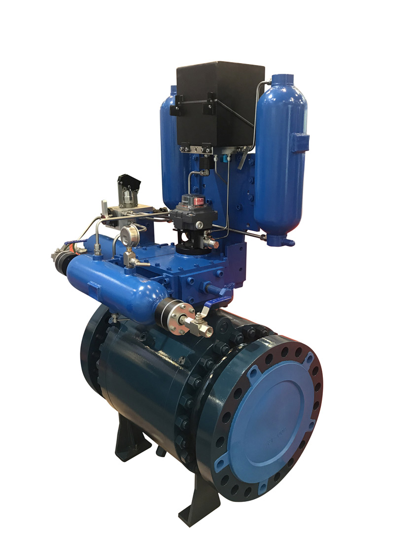
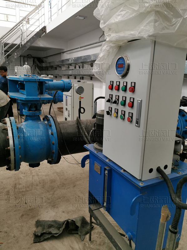
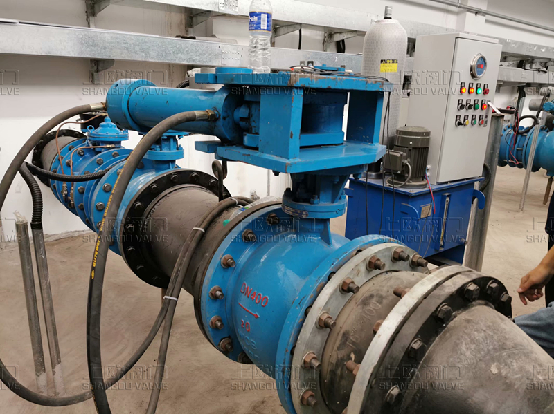
Valve body
Transmission device (connected with valve body)
Hydraulic station (separate installation with valve)
Electrical control box (integral installation with hydraulic station)
When ordering, please specify the product name, model, specification, maximum and minimum working pressure, medium, temperature, installation type (front or reverse installation, horizontal installation or vertical installation) and other electro-hydraulic control requirements, so that we can provide satisfactory products that fully meet your needs according to your actual working conditions.
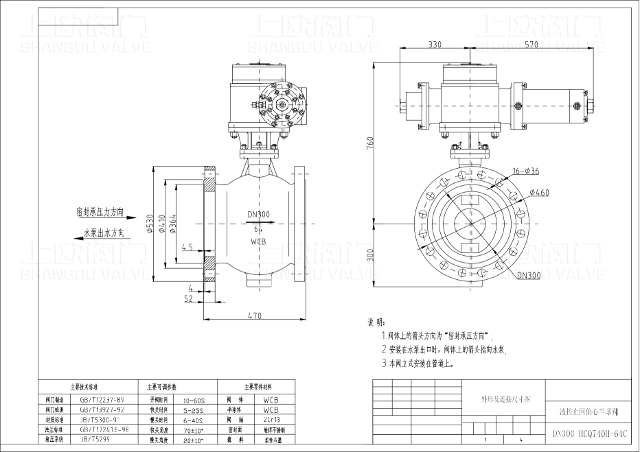
Valve outline drawing
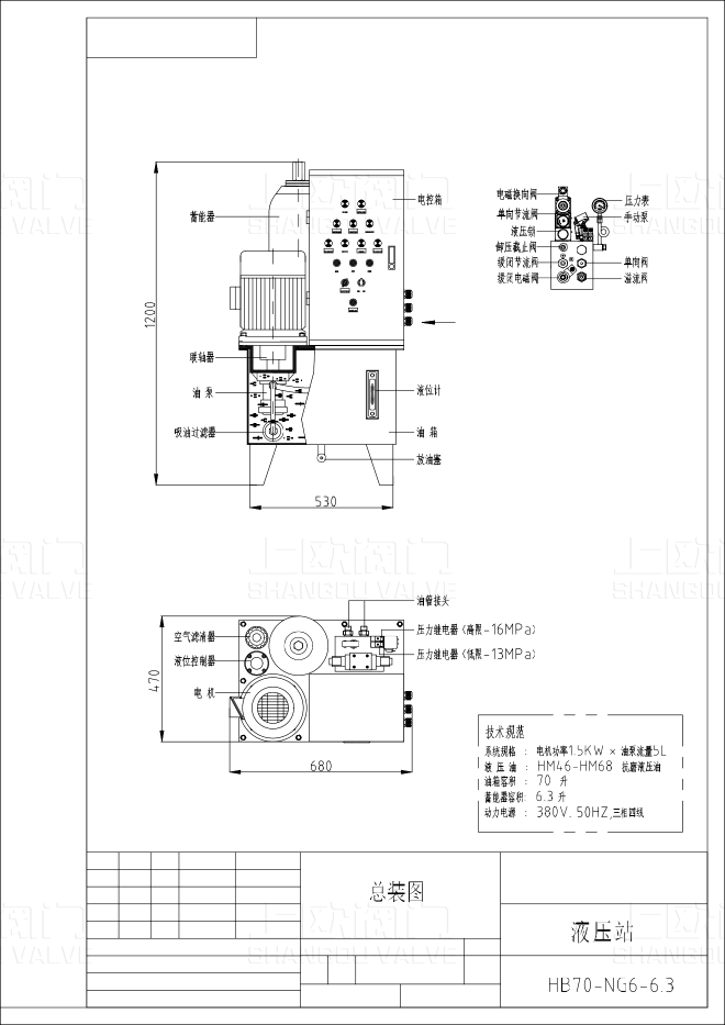
Outline drawing of hydraulic station
Schematic diagram of hydraulic station
Electrical schematic diagram
常用阀门材料允许使用压力明细介绍
常用阀门材料允许使用压力明细说明。常用阀门材质国家标准代号分类
常用阀门材质国家标准代号分类有那些,上欧为您做准确说明,请参.....What is the name.....
The name of the organization t.....Main technical r.....
The main technical requirement.....Bill of material.....
1: Screw plug: Bronze / stainl.....Set up a new ben.....
Full flow streamline design, t.....General technica.....
The adjustment of piston type .....Fast Navigation
Product Line
Recommended Products
Technical Support
Copyright:Shangou Valve Co.,Ltd Record No:; Sitemap
Friendship Links: SenAu Product website