0577-67975099
 QQ
QQ WeChat
 邮箱
邮箱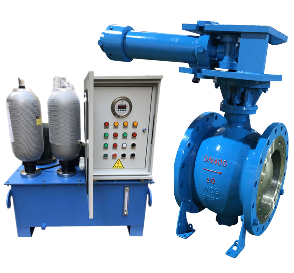
Telephone:
0577-67975099
 Location:Home > Product Center > Air Valve > HD7X41XHydraulic control slow closing check butterfly valve with accumulator typePN6~PN16
 Telephone:
0577-67975099
Telephone:
0577-67975099

The control characteristics of electromagnetic directional valve in hydraulic system are generally positive, that is, the solenoid valve is powered on butterfly valve, and the valve is closed after power failure; otherwise, it is reaction type, namely, the solenoid valve is opened when the power is off, and the valve is closed when the power is on. Conventional matching electromagnetic directional valve is positive action type, the use of boring type should be explained when ordering!
1、 Characteristics of hd7x41x accumulator type hydraulic control slow closing check butterfly valve
1. The valve can be closed automatically when there is no external energy.
2. The sealing is reliable and the flow resistance coefficient is small.
3. The PLC intelligent control system can realize the text, touch screen and other humanized operation interfaces.
4. It can realize remote and local control.
5. Be able to realize linkage operation with other pipeline equipment according to predetermined procedures.
6. It has fast and slow adjustable closing function.
7. With cut-off and check function.
8. It can realize the function of slow closing when closing, effectively eliminate the harm of water hammer, and protect the safety of water pump and network management system.
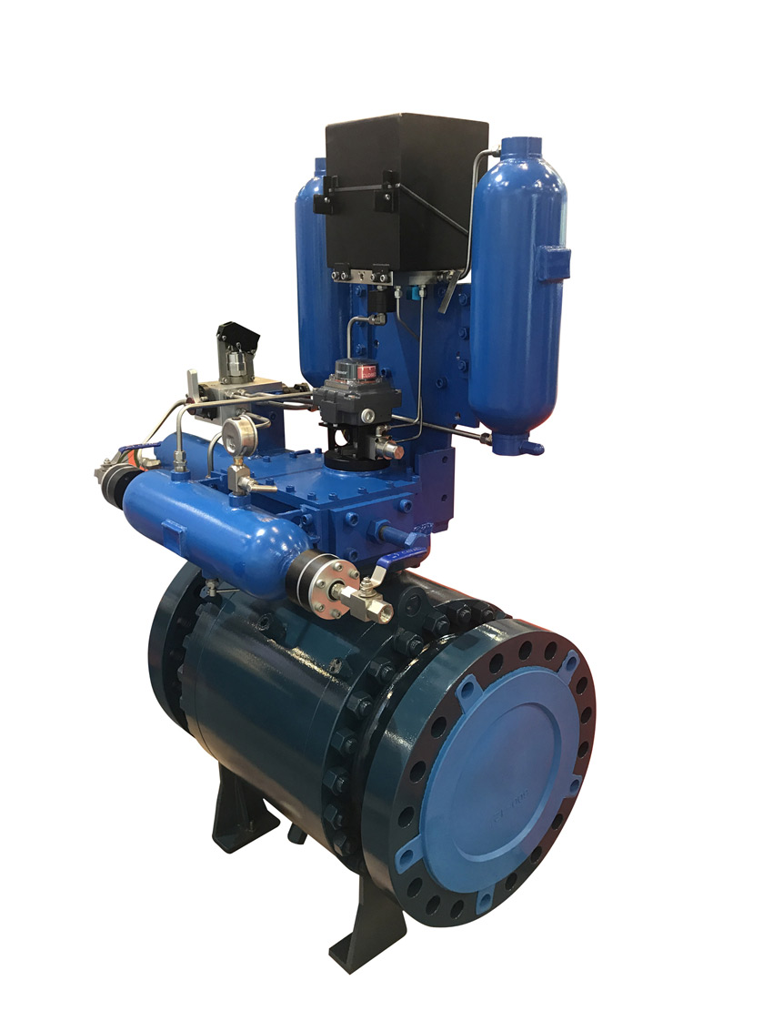
2、 According to the control system, it can be divided into ordinary accumulator type (x) and accumulator type locking type (XS)
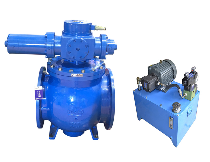
1. It is mainly composed of valve body, transmission mechanism, hydraulic station and electric control box
2. The valve body is composed of valve body, disc plate, valve shaft, sealing components and other parts.
3. The transmission mechanism is mainly composed of hydraulic cylinder, rocker arm, support side plate and other connection and transmission parts, which is the main actuator of opening and closing valves by hydraulic power.
4. The hydraulic station includes oil pump unit, manual pump, accumulator, solenoid valve, overflow valve, flow control valve, stop valve, hydraulic manifold block, oil tank and other parts.
5. Manual pump is used for system debugging and valve opening and closing under special working conditions.
6. The flow control valve is used to adjust the valve opening time.
7. The transmission hydraulic cylinder is equipped with quick closing time regulating valve, slow closing time regulating valve and fast and slow closing angle adjustment.
8. In the system, the two accumulators are standby for each other to provide the active power source for the valve opening and closing.
9. The valve shaft can be of long or short shaft structure.
10. Horizontal layout is generally adopted; vertical layout can also be adopted according to user requirements.
11. The hydraulic station, electric control box and valve body can be installed as a whole or separately. If the user does not make any special instructions, it is integrated. When vertical arrangement is adopted, they are all installed separately.
12. The control characteristics of the solenoid directional valve in hydraulic system are generally positive, that is, the solenoid valve is powered on butterfly valve and the butterfly valve is closed when the power is off; otherwise, it is the reaction type, that is, when the solenoid valve is de energized, the butterfly valve is opened and the butterfly valve is closed when it is powered on. Conventional matching electromagnetic directional valve is positive action type, the use of boring type should be explained when ordering!
HD7X41X Connection dimensions of pn6 ~ PN16 type accumulator type hydraulic control slow closing check butterfly valve(mm)
| DN | PN | L | L1 | L2 | L3 | L4 | Flange connection size |
| 400 | 0.6 | 216 | 556 | 1449 | 320 | 440 | GB/T17241 GB/T9113 |
| 1.0 | 216 | 556 | 1449 | 330 | 440 | ||
| 1.6 | 216 | 556 | 1449 | 345 | 440 | ||
| 450 | 0.6 | 222 | 556 | 1449 | 370 | 440 | |
| 1.0 | 222 | 556 | 1449 | 380 | 440 | ||
| 1.6 | 222 | 580 | 1449 | 395 | 490 | ||
| 500 | 0.6 | 229 | 580 | 1449 | 400 | 440 | |
| 1.0 | 229 | 580 | 1449 | 410 | 490 | ||
| 1.6 | 229 | 580 | 1449 | 425 | 490 | ||
| 600 | 0.6 | 267 | 580 | 1449 | 440 | 490 | |
| 1.0 | 267 | 580 | 1449 | 460 | 490 | ||
| 1.6 | 267 | 625 | 1820 | 470 | 490 | ||
| 700 | 0.6 | 292 | 625 | 1449 | 436 | 490 | |
| 1.0 | 292 | 625 | 1820 | 550 | 545 | ||
| 1.6 | 292 | 625 | 1820 | 570 | 545 | ||
| 800 | 0.6 | 318 | 625 | 1820 | 625 | 490 | |
| 1.0 | 318 | 625 | 1820 | 640 | 545 | ||
| 1.6 | 318 | 625 | 1820 | 660 | 545 | ||
| 900 | 0.6 | 330 | 625 | 1820 | 700 | 545 | |
| 1.0 | 330 | 625 | 1820 | 710 | 545 | ||
| 1.6 | 330 | 675 | 1820 | 725 | 610 | ||
| 1000 | 0.6 | 410 | 625 | 1820 | 760 | 610 | |
| 1.0 | 410 | 675 | 1820 | 770 | 610 | ||
| 1.6 | 410 | 675 | 2180 | 790 | 610 | ||
| 1200 | 0.6 | 470 | 675 | 1820 | 875 | 610 | |
| 1.0 | 470 | 675 | 2180 | 890 | 610 | ||
| 1.6 | 470 | 729 | 2180 | 915 | 720 | ||
| 1400 | 0.6 | 530 | 729 | 2180 | 1000 | 720 | |
| 1.0 | 530 | 729 | 2180 | 1020 | 720 | ||
| 1.6 | 530 | 781 | 2180 | 1045 | 960 | ||
| 1600 | 0.6 | 600 | 781 | 2180 | 1120 | 720 | |
| 1.0 | 600 | 781 | 2180 | 1140 | 960 |

1. Before installation, check whether the specification, pressure, temperature and corrosion resistance of butterfly valve meet the use requirements. Check whether the parts are damaged or loose.
2. The butterfly valve can be installed on the pipeline at any angle and should be closed; when welding the pipe flange, the valve sealing port should be blocked with a plate to prevent particles and sundries from damaging the sealing surface. After welding, take down the valve, clean the valve sealing surface and pipe cavity, and then install the fixed valve.
3. Please pay attention to the pressure bearing direction when the valve is closed.
4. Before installation, the sealing surface (sealing surface at both ends, sealing surface of butterfly plate and sealing surface of valve seat) shall be thoroughly cleaned to remove dust and dirt.
5. Before installation, the butterfly valve should be air tested, and the opening and closing position should be flexible, and the opening and closing position should be consistent with the position indicated by the pointer.
6. Manual operation, clockwise is off, counter clockwise is on, pointer indication is in place, it is not allowed to open and close the valve with additional force.
7. During the pressure test of the valve, it is not allowed to use single flange for installation and pressure test, but double flange installation and pressure test must be adopted. The test pressure shall comply with GB / T13927-92.
8. The bolts shall be tightened symmetrically and alternately instead of separately.
9. The limit screw has been adjusted before delivery, so it is not allowed to adjust it easily. Please refer to the manual for electric drive device.
10. When the electric butterfly valve leaves the factory, the opening and closing stroke of the control mechanism has been adjusted. In order to prevent the wrong direction when the power supply is connected, the user should first manually open it to the half open position before connecting the power for the first time, and then press the inching switch to check that the direction of the indicator wheel is consistent with the opening direction of the valve.
11. If the valve is found to be open and closed abnormally, the cause shall be found out for repair and elimination, so as to prevent the valve from being damaged due to opening and closing by means of applying force.
常用阀门材料允许使用压力明细介绍
常用阀门材料允许使用压力明细说明。常用阀门材质国家标准代号分类
常用阀门材质国家标准代号分类有那些,上欧为您做准确说明,请参.....What is the name.....
The name of the organization t.....Main technical r.....
The main technical requirement.....Bill of material.....
1: Screw plug: Bronze / stainl.....Set up a new ben.....
Full flow streamline design, t.....General technica.....
The adjustment of piston type .....Fast Navigation
Product Line
Recommended Products
Technical Support
Copyright:Shangou Valve Co.,Ltd Record No:; Sitemap
Friendship Links: SenAu Product website