0577-67975099
 QQ
QQ WeChat
 邮箱
邮箱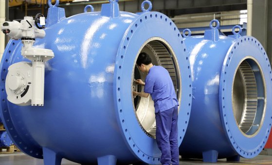
Telephone:
0577-67975099
 Location:Home > Product Center > Plug Valve > BFTZType V conical relief valve
 Telephone:
0577-67975099
Telephone:
0577-67975099

Conical relief valve is the latest product developed and produced by our company absorbing foreign technology in China. It is usually used as the free discharge valve of bypass valve of hydraulic turbine generator set or continuous discharge flow control valve of hydropower station and reservoir. It has excellent energy dissipation effect, so it is called release valve or energy dissipation valve. Because of the use of solid cone shape in the flow channel, it is named as fixed cone valve. In addition to the conical valve core at the end of the flow channel, all moving parts of the valve are set outside the flow passage of the valve, which makes the internal flow channel of the valve body smooth, with large flow rate and less pressure drop loss, which will not produce cavitation and vibration in the whole working range.

Model example:
|
BFTZ941YX—P |
Stainless steel electric type flange connection soft and hard double sealing conical relief valve |
|
BFTZ342YX—10C |
Cast steel manual flange connection hard and soft double sealing conical relief valve |
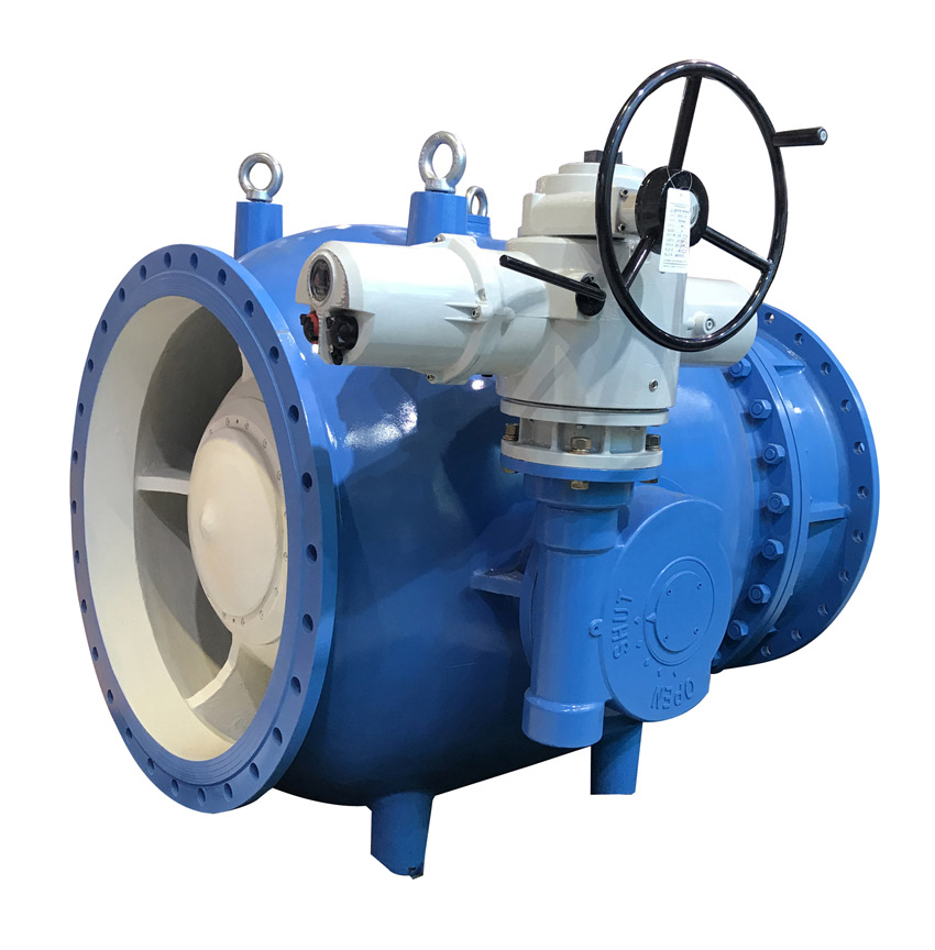
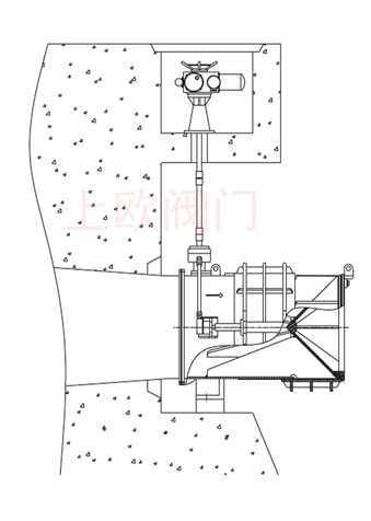
Conical relief valve is an axial flow control valve, which is composed of valve barrel, guide rib, cone, adjusting sleeve and fairing. The regulating sleeve made of stainless steel is installed on the valve body through the guide rib, and the actuator drives the sleeve to adjust the flow area of the valve.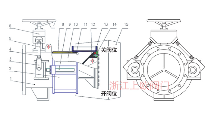
1. Valve body 2, adjusting sleeve 3, worm gear box 4, universal joint 5, transmission shaft 6, gear box 7, hand wheel 8, guide rib 9, screw rod 10, guide rib 11, O-ring 12, cone 13, seal ring 14, seat ring 15, fairing
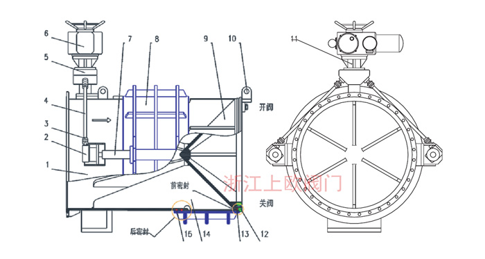
1. Valve body 2, worm gear box 3, universal joint 4, transmission shaft 5, gear box 6, electric actuator 7, screw rod 8, adjusting sleeve 9, cone 10, lifting ring 11, bracket 12, seat ring 13, sealing ring 14, guide rib 15, O-ring rubber ring
| Adaptive medium | Water, sewage and other neutral liquid, can adapt to the medium with high impurity content |
| Adaptive temperature |
-29℃——80℃ |
| Test standard | Comply with GB / t13927 standard Valve strength 1.5xpn seal test 1.1xpn |
| Flange standard | Steel flange gb9113.1-4 or according to customer requirements |
| Pressure range |
0.6-1.6MPa |
| Part name | texture of material | Part name | texture of material |
| Body / cone | Carbon steel bad embroidery steel | Guide rib surface |
Tin bronze CuAl1ONi5Fe4 |
| Adjusting sleeve | Carbon steel + stainless steel | Gearbox | Stainless steel + carbon steel |
| O-ring / rubber ring |
Isoprene rubberEPDM |
Worm gear box | Stainless steel + carbon steel |
| Seat ring | Stainless steel 316 + Ni alloy | Bracket | Carbon steel WCB |
| Drive shaft / screw | Stainless steel 2Crl3 | Fairing | Stainless steel 304 |
1. Valve body
The valve body is of cylindrical design with a flange connected to the upstream channel or pipe. The metal conical seat ring at the downstream end is of floating structure to isolate the stress caused by the deformation of the valve body. The cone at the front end of the valve is fixed in the valve body by the guide rib, and the regulating sleeve can slide freely on the rib. The valve is equipped with front and rear seals to prevent leakage during closing and operation. The sealing structure is as follows:
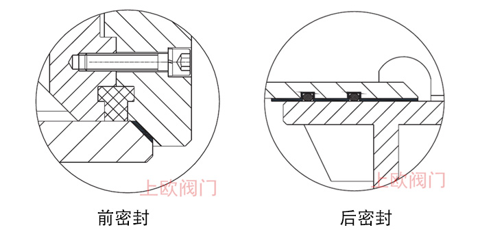
The rear sealing structure adopts double EPDM ring, which is durable; the front seal is soft and hard double sealing structure, and the soft seal is annular sealing form, which can effectively avoid the high-speed scouring of cone mouth and improve the service life. The sealing structure is detachable, easy to maintain and replace.
2. Adjusting sleeve
The regulating sleeve is cylindrical, and the valve is opened and closed by linear movement along the axis direction. The nozzle surface at the front end of the sleeve is hardened, which can effectively adapt to high velocity erosion. When the adjusting sleeve stroke ends, it contacts the seat ring to form a hard and soft double seal.
3. Fairing
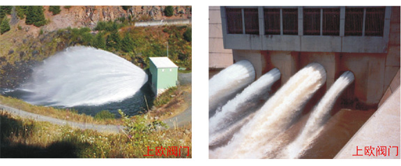
When it is necessary to guide the discharged water flow, an inflatable fairing can be installed on the cone fixed at the front end of the valve body. The fairing can control the dispersion of the jet, prevent the water from falling on the valve, let the water flow concentrate to the downstream, and have part of the energy dissipation effect on the water flow.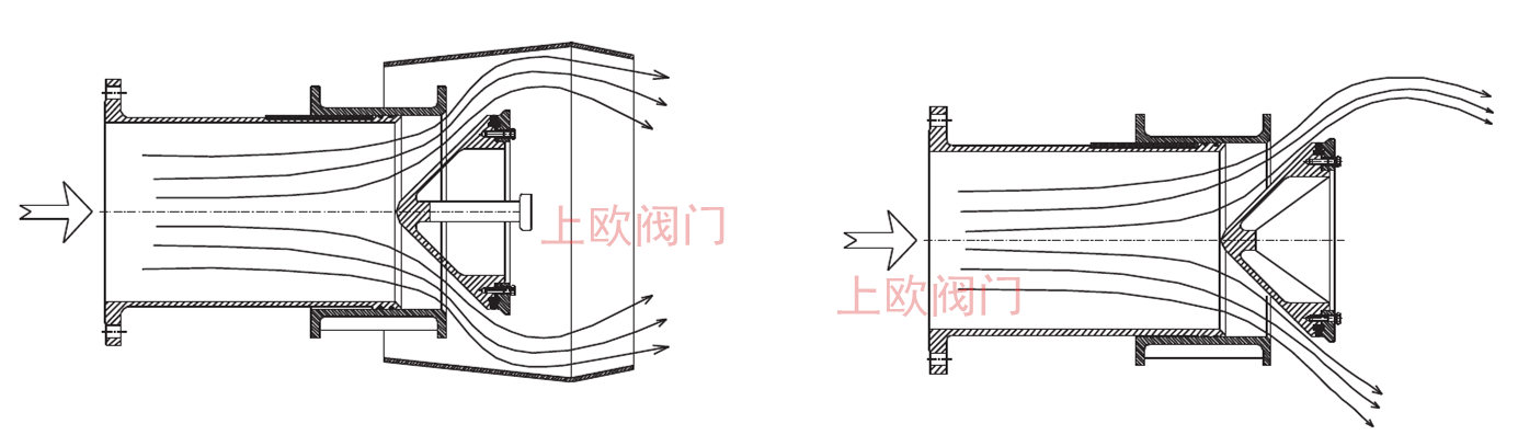 Flow diagram with and without fairing (in general, the flow coefficient of valve will be slightly reduced by 2-3% with fairing)
4. The driving device conical relief valve can be driven by electric, hydraulic cylinder or manual according to the working conditions.
The valve can adopt manual, electric, hydraulic and pneumatic operating mechanisms according to the requirements of users and sites. In addition to manual type, the following control modes can be adopted for other driving modes:
1. The flowmeter outputs 4-20mA DC signal to calibrate the corresponding minimum flow value and maximum flow value.
2. The output feedback signal of the flowmeter is sent to PLC for processing, and the corresponding control signal is output to the regulating actuator after the preset value of PLC is compared, and the valve is driven to the corresponding position (valve opening).
3. PLC is responsible for opening reservation, feedback signal comparison and control, output work. The regulating actuator is responsible for driving the valve to the specified position according to the PLC instruction, and the control precision is set by PLC. This method is closed-loop control, stable and reliable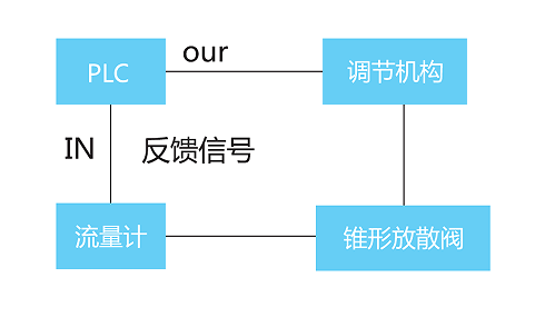
The layout of conical relief valve is closely related to the pivotal buildings, so it must be arranged scientifically and constructed carefully. When designing the layout, it is necessary to consider the windward and leeward of the system, the angle of outflow is elevation and dive, and the form of outflow is surface flow or submergence. If the layout is not appropriate, it will cause the scour of the surrounding buildings and downstream riverbed caused by the jet generated when the valve is opened, especially when the opening is small, and the water mist formed during the operation will affect the power station equipment and valve parts. Valve installation must be standardized to reduce the vibration of the system caused by valve drainage. It is suggested that according to the landform and actual situation, the arrangement of conical valve should be arranged reasonably from three aspects: outlet mode, installation mode and divergence mode.
1. The choice of exit mode:
(1) submerged type: it is suitable for irrigation or drinking water system such as ditches with low water head. The outlet is wide and flat, mainly in sand and stone terrain;
(2) jet type: suitable for high water head and steep mountain;
2. Selection of installation mode:
(1) Horizontal installation: it is suitable for the weak energy dissipation pool, but the site is wide and there are no buildings around;
(2) Vertical installation: suitable for narrow site or more buildings close to each other.
(3) Optional angle installation: usually between horizontal and vertical installation.
3. Choice of divergence form:
(1) General type (free divergence type): it is free to diverge in the air and forms different divergence areas according to the size of water head;
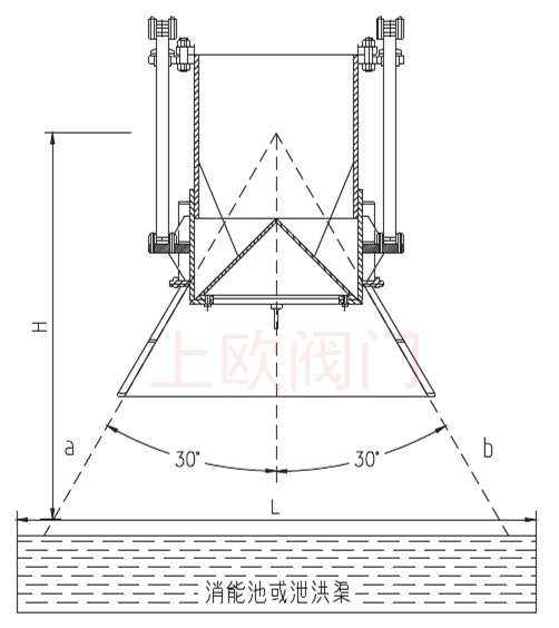
(2) The type with fairing (limited divergence type): use the deflector to effectively control the outlet divergence of the conical valve: they are used for high water head and narrow outlet, involving buildings or other facilities; as shown in the figure, the user should select the appropriate deflector according to the specific size of the designed energy dissipation basin or flood discharge channel, as shown in the figure B is the extension line of the included angle of the diversion cover, l is the width of the energy dissipation basin or flood discharge channel, and H is the height from the top of the included angle of the diversion cover to the surface of the energy dissipation basin or flood discharge channel. The angle of the selected deflector is calculated according to the principle of equilateral triangle.
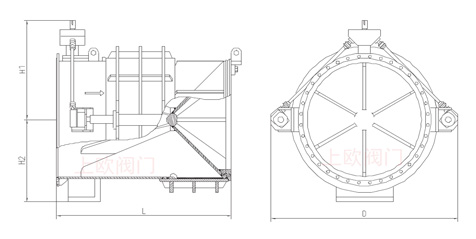
|
DN |
200 |
300 |
400 |
450 |
500 |
600 |
700 |
900 |
1000 |
1100 |
1200 |
1300 |
1400 |
1500 |
1600 |
1800 |
2000 |
|
L |
570 |
720 |
940 |
980 |
1120 |
1240 |
1350 |
1600 |
1780 |
1900 |
2100 |
2250 |
2350 |
2400 |
2560 |
2800 |
2900 |
|
HI |
280 |
320 |
480 |
500 |
540 |
580 |
680 |
740 |
860 |
950 |
1020 |
1100 |
1200 |
1350 |
1420 |
1500 |
1820 |
|
H2 |
220 |
300 |
380 |
420 |
450 |
480 |
510 |
600 |
720 |
780 |
840 |
890 |
920 |
1030 |
1150 |
1240 |
1450 |
|
D |
450 |
600 |
1000 |
1000 |
1160 |
1250 |
1400 |
1600 |
1900 |
2200 |
2300 |
2580 |
2580 |
2700 |
2780 |
2820 |
3100 |
|
重量Kg |
380 |
410 |
490 |
520 |
580 |
950 |
1150 |
1750 |
2000 |
2500 |
3600 |
4400 |
5100 |
5900 |
6700 |
8900 |
9900 |
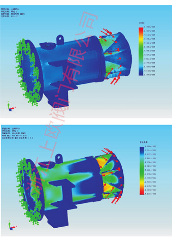
The cone relief valve can control the flow by changing the flow area between the regulating sleeve and the cone, so that the valve can discharge freely under any opening, and the cavitation and vibration can be controlled to the minimum. Through scientific fluid design, CosmosWorks structural analysis software is used to determine the valve stress distribution, and advanced fluent fluid analysis software is used to test the cone. The linear corresponding relationship between the change of flow surface and the movement of the regulating sleeve is formed, and the good regulation performance of the whole stroke is realized. Compared with other conventional energy dissipation valves, the cone is fixed on the valve body by several streamlined rib plates, which can significantly reduce or eliminate the cavitation and vibration of the valve during operation, and minimize the operating torque of the valve. When the valve is closed, the regulating sleeve and the conical valve seat at the front end of the cone form a metal to metal and metal to rubber double seal to ensure zero leakage of the valve. When the valve is opened, the discharged water flows into the atmosphere with a wide cone angle, and is decomposed into fine droplets. If the shape of jet flow needs to be controlled, an inflatable fairing can be added at the outlet of the valve, which not only allows air to mix into the water, but also forms a concentrated water flow shape.
Calculation method of model selection
The valve diameter can be calculated according to the required flow rate, and the flow calculation formula is as follows:
Q = flow rate (m3 / s)
CV = flow coefficient (the valve has good hydraulic condition and has higher flow coefficient than other valves, CV = 0.75 ~ 0.86) g = 9.81 (M / S2)
H = total head in front of conical relief valve relative to valve body axis (m)
A = cross sectional area of poppet valve (M2)
常用阀门材料允许使用压力明细介绍
常用阀门材料允许使用压力明细说明。常用阀门材质国家标准代号分类
常用阀门材质国家标准代号分类有那些,上欧为您做准确说明,请参.....What is the name.....
The name of the organization t.....Main technical r.....
The main technical requirement.....Bill of material.....
1: Screw plug: Bronze / stainl.....Set up a new ben.....
Full flow streamline design, t.....General technica.....
The adjustment of piston type .....Fast Navigation
Product Line
Recommended Products
Technical Support
Copyright:Shangou Valve Co.,Ltd Record No:; Sitemap
Friendship Links: SenAu Product website