0577-67975099
 QQ
QQ WeChat
 邮箱
邮箱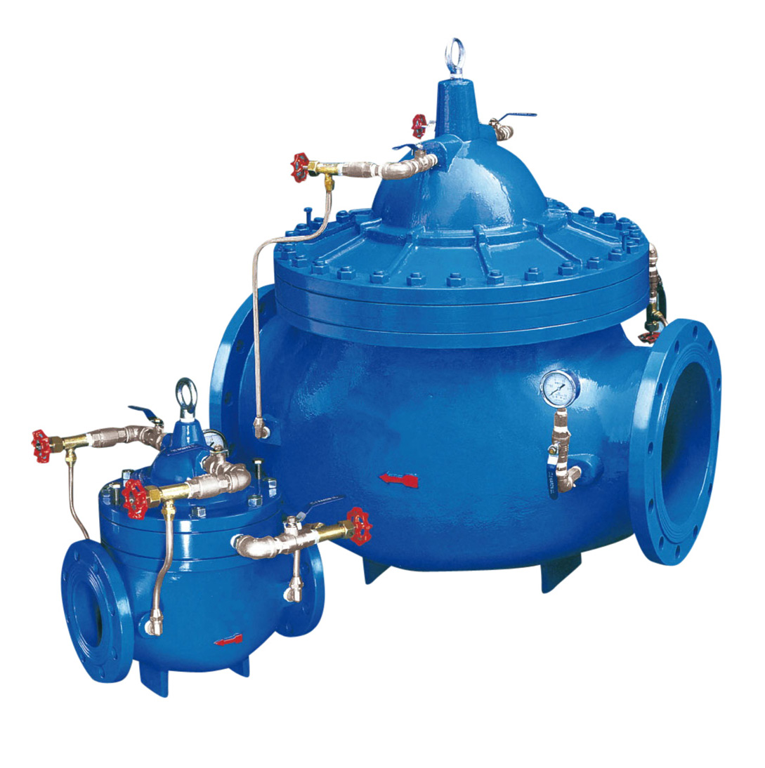


Telephone:
0577-67975099
 Location:Home > Product Center > Hydraulic Control Valve > JD745XMulti function piston valve for water pump
 Telephone:
0577-67975099
Telephone:
0577-67975099
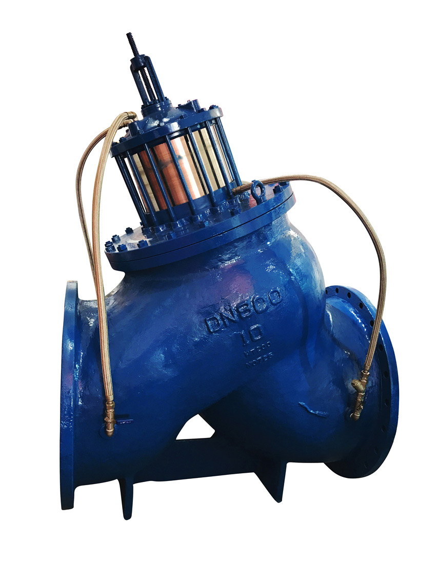
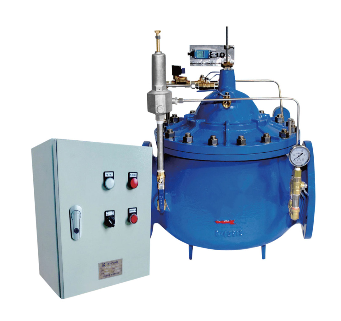
JD745XThe main feature of piston type multi-function water pump control valve is to control the opening and closing of the main valve disc through the pressure difference between the upper and lower chambers by using the pressure of the pipe itself, so as to achieve the purpose from the surface. Piston type multifunctional pump control valve is an intelligent valve installed at the pump outlet of large diameter water supply network system to prevent the phenomenon of backflow of medium, water hammer and water hammer.
The main feature of piston type multi-function water pump control valve is to control the opening and closing of the main valve disc through the pressure difference between the upper and lower chambers by using the pressure of the pipe itself, so as to achieve the purpose from the surface. Piston type multifunctional pump control valve is an intelligent valve installed at the pump outlet of large diameter water supply network system to prevent the phenomenon of backflow of medium, water hammer and water hammer.
The working pressure of piston type multi-function water pump control valve is divided into six types: 1.0MPa, 1.6Mpa, 2.5MPa, 4.0Mpa, 6.4Mpa and 10.0MPa. The operating pressure is greater than or equal to 0.03mpa, the medium temperature is 0-80 ℃, the slow closing time can be adjusted within 3-120s, the pressure loss of pipeline flow rate of 2m / S is less than 0.01Mpa, and the peak value of water hammer is less than 1.5 times of working pressure
Working principle of piston type multifunctional water pump control valve
The piston type multi-function pump control valve has three functions: electric valve, check valve and water hammer elimination, which can effectively improve the safety and reliability of the water supply system. The double chamber and double valve flap structure can make the valve quickly close 90% after the pump stops (prevent the reverse of the pump caused by the backflow medium), and then slowly close the remaining 10% (eliminating the destruction of water hammer) piston valve with reliable performance, high strength and dynamic It is stable and suitable for the occasion of starting and stopping water hammer. The valve can be opened and closed automatically according to the pump operation regulations by operating the pump motor open and close button, with large flow and small pressure loss.
Features and advantages
The piston type multi-function water pump control valve has the function of slow opening, which solves the traditional manual valve closing and pump starting.
The piston type multi-function water pump control valve has the function of slow closing, which can adjust the closing time manually to automatically realize slow closing and eliminate water hammer.
The piston type multi-function water pump control valve has good check function. The rubber sealing material with good elasticity and high wear resistance is used to ensure no water leakage after closing.
Piston type multi-function water pump control valve is sensitive and will not be out of control.
The piston type multi-function pump control valve does not need to be operated manually, and it works automatically in the whole process of pipe network operation.
The control valve of piston type multi-function water pump is easy to maintain, without the need to remove the valve from the whole pipe. In maintenance, find out the cause of failure, and only need local maintenance.
The inside and outside of the control valve of the piston type multi-function water pump and all the easily corroded parts are treated by electrostatic spraying, which will not rust in the sewage for a long time.
The piston type multi-function water pump control valve can be installed in the neutral position of the pipeline with the same performance.
It is installed in the pumping station of water intake, water delivery, pressurization, diving, sewage pump room and oil and chemical fluid transportation system in the fields of municipal administration, construction, iron and steel, metallurgy, petroleum, chemical industry, gas (natural gas), food, medicine, mine, power station, nuclear power, water conservancy and irrigation. It integrates the functions of electric valve, check valve and water hammer eliminator, which can effectively improve the system The system is safe and reliable to meet the requirements of system automation control.
1. It has three measures to eliminate water hammer, including quick closing, slow closing and energy absorbing chamber, and the action is fully interlocked, without misoperation.
2. There is no need for operation control. When the water pump starts and stops, the pressure change of the medium before and after the valve is used to control the power, so that the valve automatically acts according to the requirements of the pump operation regulations.
3. Without professional debugging, the valve action is not affected by the change of pump head and flow, so it can be used in a wide range.
4. Basically no maintenance, long life.
5. The energy-saving effect is obvious. The pressure at the inlet end enters into the lower chamber of the diaphragm to support the weight of the diaphragm pressing plate and the valve rod, and the resistance loss is small.
1. Nominal pressure: 1.0MPa, 1.6Mpa, 2.5MPa, 4.0Mpa, 6.4Mpa, 10.0MPa
2. Minimum operating pressure: 0.05Mpa
3. Applicable media: raw water, sea water, sewage and oil
4. Applicable temperature: 0 ~ 80 ℃
5. Slow closing time: 3 ~ 120s (adjustable)
6. Peak value of water hammer: ≤ 1.3 times of rated pressure at pump outlet
7. Maximum reverse speed of water pump: ≤ 1.2 times of rated speed of water pump
8. Fatigue bending of diaphragm: 1.2 million times without damage
1、Normal operation process control diagram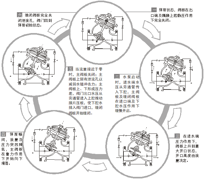
Installation precautions (see 11 for structural type and installation diagram)
1. Before installation, please check whether all parts of the main valve are in good condition and the fasteners are complete without looseness.
2. Check whether the connecting pipelines are in good condition and the joints are tight.
3. Ensure that the minimum operating pressure meets the requirements of technical parameters.
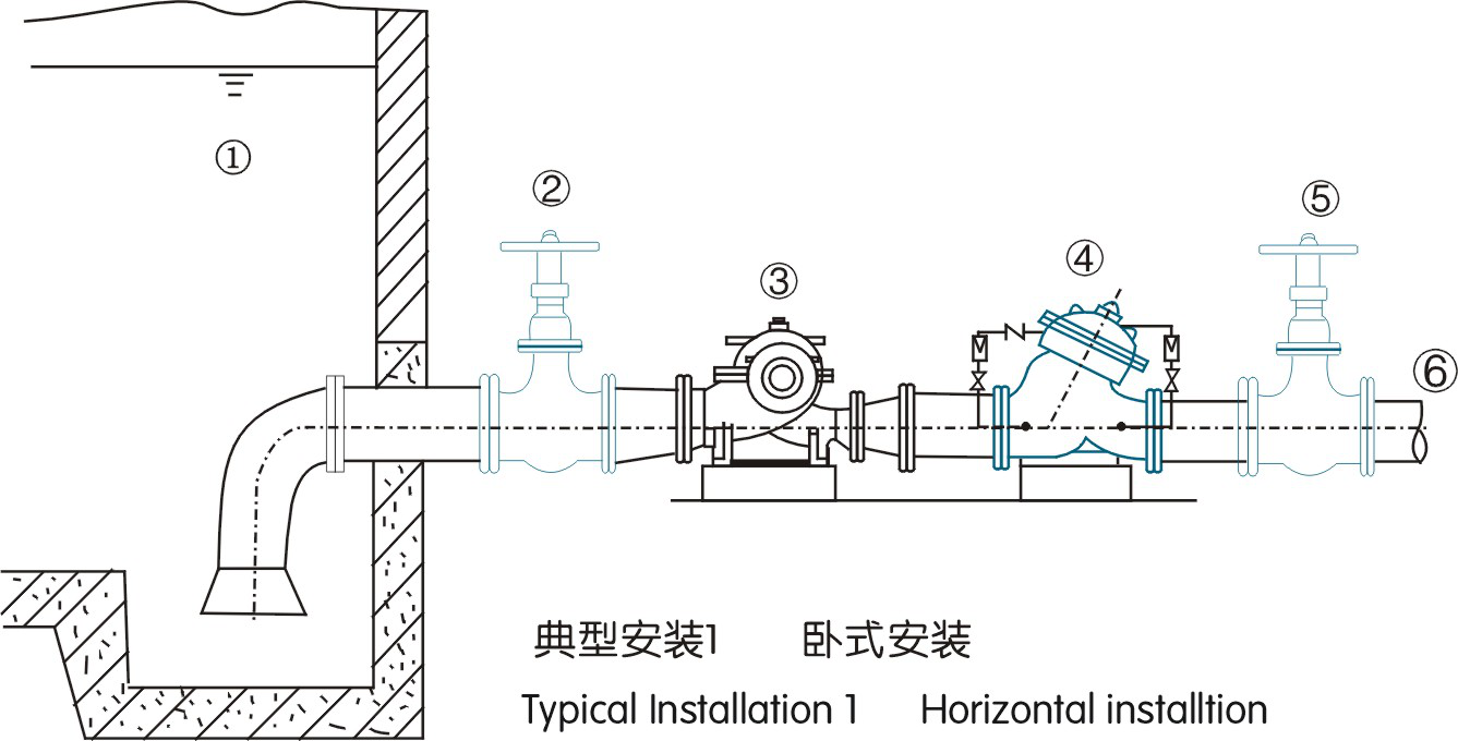
4. The best installation method is to install the main valve on the horizontal pipeline with the valve cover upward. (typical installation 1)
5. If the main valve is installed in the well, a certain space should be reserved for the maintenance of technicians.
6. During installation, please pay attention to the direction indicated by the arrow on the valve body, and do not install in reverse.
7. If it is necessary to carry out commissioning and observe the working pressure, a pressure gauge must be installed at the inlet and outlet.
8. Regular start-up inspection shall be conducted for fire-fighting to prevent scale and valve failure.
9. Exhaust valve must be installed for deep well pump. (typical installation 3)
10. Please do not use the control pipe to lift or damage the control pipe during hoisting and handling.
11. When other valves are installed at the outlet of multi-functional water pump control valve, a certain distance must be kept.
1. During installation, pay attention to check and clean the pipeline, and there shall be no welding slag, bolts and other foreign matters.
2. Pipe installation shall be installed with inlet and exhaust valves and other devices according to relevant specifications to ensure no water column interruption.
3. The flexible joint should not be installed at the inlet end of the valve.
4. For the pumping station that may produce water hammer of water column separation, the calculation of water hammer during pump stop should be carried out.
1. Open the valves a and E on the control pipe and start the pump.
2. Start the pump and observe whether there is water leakage in the pipe fittings and whether the pressure at the inlet and outlet of the valve is normal.
3. Then open the exhaust valves D and F to discharge the air from the upper and lower chambers, and repeat for many times until no air is discharged.
4. Slow closing time adjustment:
The slow closing time can be realized by adjusting the opening of control valve E on the bypass pipe. The control valve should be reduced first to extend the slow closing time.
If the slow closing time is too long, the opening of control valve e will be increased.
If the slow closing time is too short, the opening of control valve e can be reduced.
If any abnormality is found, please handle it according to table 2 or contact our company directly.
| nominal Diameter |
L |
H |
H1 |
D |
D1 |
N-d |
Reference weight(Kg) |
|||||||||||||||||||||
|
1.0 |
1.6 |
2.5 |
4.0 |
6.4 |
10 |
1.0 |
1.6 |
1.0 |
1.6 |
2.5 |
4.0 |
6.4 |
10 |
1.0 |
1.6 |
2.5 |
4.0 |
6.4 |
10 |
1.0 |
1.6 |
2.5 |
4.0 |
6.4 |
10 |
|||
|
50 |
240 |
240 |
250 |
265 |
|
|
270 |
|
|
165 |
165 |
165 |
165 |
|
|
125 |
125 |
125 |
125 |
|
|
4-18 |
4-18 |
4-18 |
4-18 |
|
|
17 |
|
65 |
300 |
300 |
300 |
330 |
|
|
340 |
|
|
185 |
185 |
185 |
185 |
|
|
145 |
145 |
145 |
145 |
|
|
4-18 |
4-18 |
8-18 |
8-18 |
|
|
26 |
|
80 |
310 |
310 |
310 |
340 |
380 |
420 |
400 |
|
|
200 |
200 |
200 |
200 |
215 |
230 |
160 |
160 |
160 |
160 |
170 |
180 |
8-18 |
8-18 |
8-18 |
8-18 |
8-22 |
8-26 |
36 |
|
100 |
320 |
320 |
350 |
370 |
400 |
460 |
440 |
|
|
220 |
220 |
235 |
235 |
250 |
265 |
180 |
180 |
190 |
190 |
200 |
210 |
8-18 |
8-18 |
8-22 |
8-22 |
8-26 |
8-30 |
52 |
|
125 |
390 |
390 |
410 400 |
420 |
460 |
510 |
460 |
|
|
250 |
250 |
270 |
270 |
295 |
315 |
210 |
210 |
220 |
220 |
240 |
250 |
8-18 |
8-18 |
8-26 |
8-26 |
8-30 |
8-33 |
70 |
|
150 |
460 |
460 |
470 |
470 |
520 |
580 |
500 |
|
|
285 |
285 |
300 |
300 |
345 |
355 |
240 |
240 |
250 |
250 |
280 |
290 |
8-22 |
8-22 |
8-26 |
8-26 |
8-33 |
12-33 |
109 |
|
200 |
500 540 |
540 |
560 |
560 |
630 |
680 |
640 |
|
|
340 |
340 |
360 |
375 |
415 |
430 |
295 |
295 |
310 |
320 |
345 |
360 |
8-22 |
12-22 |
12-26 |
12-30 |
12-36 |
12-36 |
153 |
|
250 |
610 |
640 |
670 |
670 |
690 |
750 |
680 |
|
|
395 |
405 |
425 |
450 |
470 |
505 |
350 |
355 |
370 |
385 |
400 |
430 |
12-22 |
12-26 |
12-30 |
12-33 |
12-36 |
12-39 |
230 |
|
300 |
700 |
750 800 |
800 |
860 |
860 |
940 |
820 |
230 |
240 |
445 |
460 |
485 |
515 |
530 |
585 |
400 |
410 |
430 |
450 |
460 |
500 |
12-22 |
12-26 |
16-30 |
16-30 |
16-36 |
16-42 |
442 |
|
350 |
800 |
850 800 |
900 820 |
940 |
960 |
1040 |
950 |
260 |
272 |
505 |
520 |
555 |
580 |
600 |
655 |
460 |
470 |
490 |
510 |
525 |
560 |
16-22 |
16-26 |
16-33 |
16-33 |
16-39 |
16-48 |
590 |
|
400 |
930 980 |
930 980 |
960 1000 |
1020 |
|
|
1150 |
295 |
565 |
580 |
620 |
660 |
|
|
515 |
525 |
550 |
585 |
|
|
16-26 |
16-30 |
16-36 |
16-36 |
|
|
850 |
|
|
450 |
1050 |
1050 |
1062 |
1100 |
|
|
1400 |
335 |
615 |
640 |
670 |
685 |
|
|
565 |
585 |
600 |
610 |
|
|
20-26 |
20-30 |
20-36 |
20-39 |
|
|
1000 |
|
|
500 |
1100 |
1140 |
1140 |
1180 |
|
|
1550 |
350 |
370 |
670 |
715 |
730 |
755 |
|
|
620 |
650 |
660 |
670 |
|
|
20-26 |
20-33 |
20-36 |
20-42 |
|
|
1200 |
|
600 |
1300 |
1350 |
1350 |
|
|
|
1600 |
410 |
440 |
780 |
840 |
845 |
|
|
|
725 |
770 |
770 |
|
|
|
20-30 |
20-36 |
20-39 |
|
|
|
1600 |
|
700 |
1520 |
1550 |
1550 |
|
|
|
1750 |
478 |
895 |
910 |
|
960 |
|
|
840 |
840 |
875 |
|
|
|
24-30 |
24-36 |
24-42 |
|
|
|
2500 |
|
|
800 |
1750 1560 |
1750 1620 |
1680 |
|
|
|
1900 |
550 |
1015 |
1025 |
|
1085 |
|
|
950 |
950 |
990 |
|
|
|
24-33 |
24-39 |
24-48 |
|
|
|
3500 |
|
|
900 |
1900 1800 |
1900 1850 |
1900 |
|
|
|
2100 |
603 |
1115 |
1125 |
|
1185 |
|
|
1050 |
1050 |
1090 |
|
|
|
28-33 |
28-39 |
28-48 |
|
|
|
5000 |
|
|
1000 |
2100 2000 |
2100 2050 |
|
|
|
|
2400 |
665 |
1230 |
1255 |
|
|
|
|
1160 |
1170 |
|
|
|
|
28-36 |
28-42 |
|
|
|
|
7500 |
|
|
1200 |
2500 2350 |
2500 2400 |
|
|
|
|
2800 |
780 |
1455 |
1485 |
|
|
|
|
1380 |
1390 |
|
|
|
|
32-39 |
32-48 |
|
|
|
|
10000 |
|
|
1400 |
3000 |
|
|
|
|
|
3400 |
890 |
1675 |
|
|
|
|
|
1590 |
|
|
|
|
|
36-42 |
|
|
|
|
|
14000 |
|
注:粗体字为新的结构尺寸系列。因产品改进,可能存在实物与宣传资料有所差异。
| Fault phenomenon | Cause failure | Rectification measures | |
| Rectification measures | Other control valve (butterfly valve, gate valve) problems | Check that other control valves are open | |
|
|
Control line problem
|
Control line problem | Cleaning pipeline filter Replace the micro check valve |
| Cleaning pipeline filter Replace the micro check valve |
Control line problem | Control line problem | Cleaning pipeline filter Replace the micro check valve |
| The main valve is not closed tightly | Is there any blockage in the pipe Is the micro check valve damaged |
Remove the foreign matters in the pipeline Replace the micro check valve |
|
|
|
Is the main valve plate jammed differently The object and seal are damaged |
After repeatedly opening and closing the main valve for several times, the water pump still has the phenomenon of reverse rotation, which is the clamping foreign body and seal damage | Remove the debris or replace the seal |
| Is the diaphragm damaged | Open the control valve a on the bypass pipe and close the control valve E; close the emptying valve f and then open the emptying valve D. if there is air or water discharged, it indicates that the valve plate is opening and the valve plate is opened in place. | Replace the diaphragm | |
| Main valve opens too fast | Micro check valve | Replace the micro check valve | |
|
|
Upper and lower diaphragm chambers and control piping |
There is too much gas | Exhaust gas |
① Pool ② ⑤ soft seal gate valve ③ water pump ④ multi function water pump control valve ⑦ exhaust valve
⑥ To water tower or user (8) deep well pump
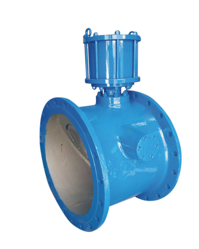
| 1. Structure: the vertical installation type is an auxiliary spring installed in the valve body of the standard multi-function water pump control valve. 2. Principle: when the main valve is installed vertically, due to the small slope of the valve stem and the slow speed of gravity sliding, it must be closed by the push of spring, which improves the reaction speed of the main valve and makes the valve plate close tightly. | 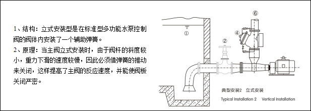 |
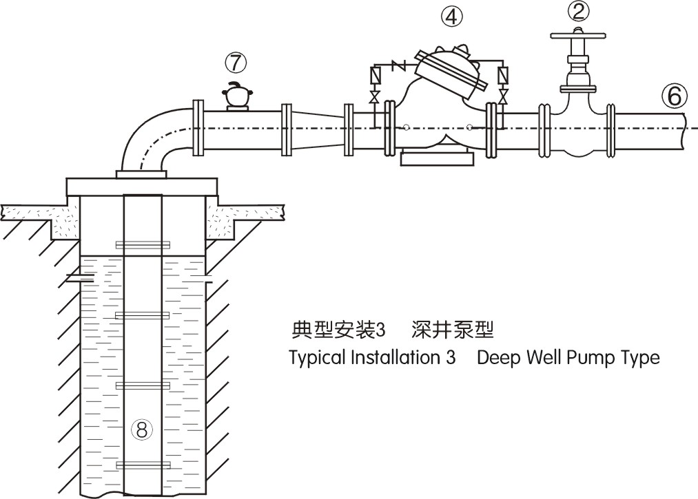 |
1. Structure: deep well pump type multi-functional water pump control valve is installed with an exhaust valve on the main valve body. |
常用阀门材料允许使用压力明细介绍
常用阀门材料允许使用压力明细说明。常用阀门材质国家标准代号分类
常用阀门材质国家标准代号分类有那些,上欧为您做准确说明,请参.....What is the name.....
The name of the organization t.....Main technical r.....
The main technical requirement.....Bill of material.....
1: Screw plug: Bronze / stainl.....Set up a new ben.....
Full flow streamline design, t.....General technica.....
The adjustment of piston type .....test
Fast Navigation
Product Line
Recommended Products
Technical Support
Copyright:Shangou Valve Co.,Ltd Record No:; Sitemap
Friendship Links: SenAu Product website