0577-67975099
 QQ
QQ WeChat
 邮箱
邮箱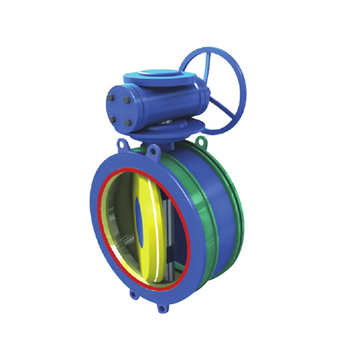
Telephone:
0577-67975099
 Location:Home > Product Center > control valve > GWXJFControl valve of type a slurry pump Ink seal
 Telephone:
0577-67975099
Telephone:
0577-67975099
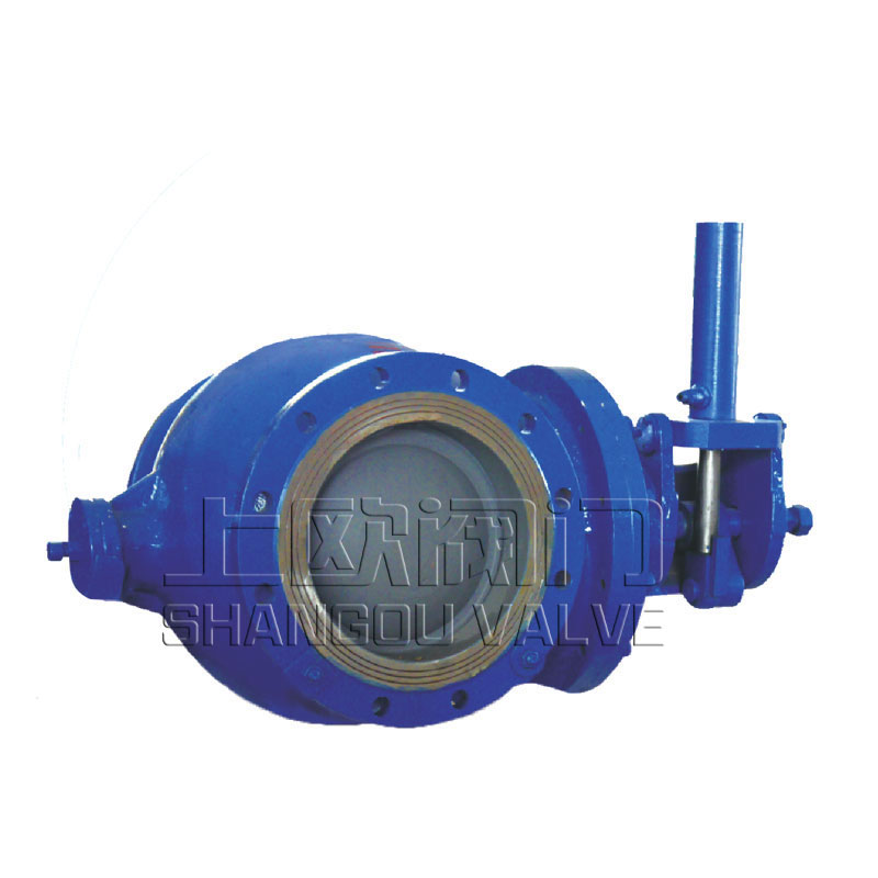
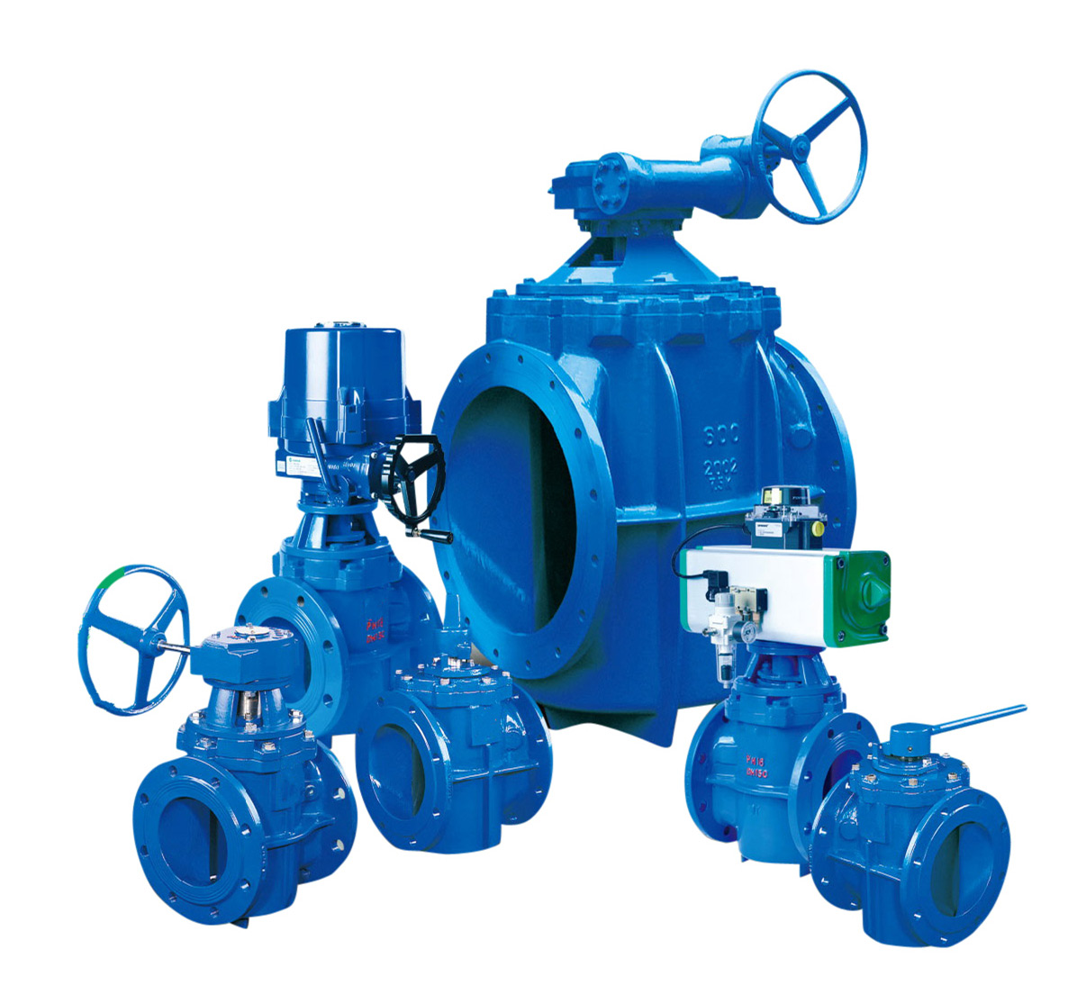
The hydraulic control slow closing check valve is an advanced pump outlet control equipment at home and abroad. It can be installed at the inlet of hydraulic turbine of hydropower station as the control valve of turbine inlet; it can also be installed at the outlet of various pumps to replace check valve, gate valve and water hammer eliminator. When working, the valve matches with the pipeline host. According to the principle of hydraulic transition process, the pre-set opening and closing procedures can effectively eliminate the water hammer in the pipe network, realize the reliable operation of the pipe network, and play a role in protecting the safety of the pipe network and pump valve equipment. However, due to the valve plate in the center of the flow channel, the butterfly valve can not avoid the erosion of the medium on the valve plate, valve shaft and valve seat sealing surface. At the same time, the valve plate hinders the flow of medium, which is easy to produce slag accumulation and sealing effect, so it can not adapt to the conditions containing slag and impurities Ink seal
The hydraulic control slow closing check valve is an advanced pump outlet control equipment at home and abroad. It can be installed at the inlet of hydraulic turbine of hydropower station as the control valve of turbine inlet; it can also be installed at the outlet of various pumps to replace check valve, gate valve and water hammer eliminator. When working, the valve matches with the pipeline host. According to the principle of hydraulic transition process, the pre-set opening and closing procedures can effectively eliminate the water hammer in the pipe network, realize the reliable operation of the pipe network, and play a role in protecting the safety of the pipe network and pump valve equipment. However, due to the valve plate in the center of the flow channel, the butterfly valve can not avoid the erosion of the medium on the valve plate, valve shaft and valve seat sealing surface. At the same time, the valve plate hinders the flow of medium, which is easy to produce slag accumulation and sealing effect, so it can not adapt to the conditions containing slag and impurities.

型号示例:
| Model example: 800gwxjf747xd hr-40c DN800 with diameter of PN4.0MPa, cast steel energy storage type single chip microcomputer control fixed shaft flange connection hard seal hydraulic control slurry valve Note: the solenoid directional valve of hydraulic system is generally of positive action type, that is, the valve is opened and closed after power failure; otherwise, it is of reaction type, that is, the valve is opened and closed after power failure. The conventional matching is positive action type, which adopts reaction type or other control forms. Please explain when ordering. |
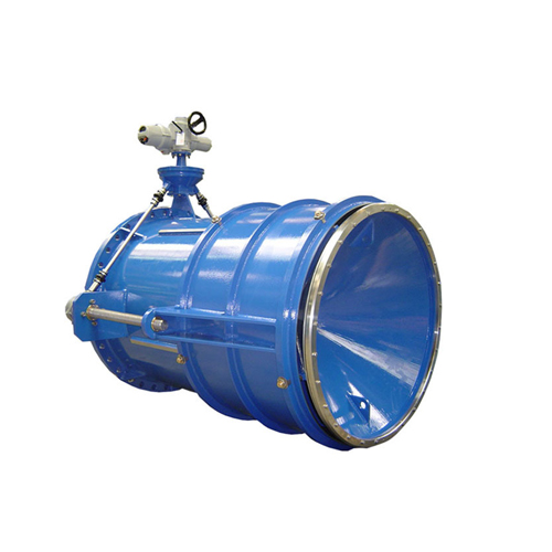
1. Wide range of application: it is widely used in the conveying control system of blast furnace water flushing slag, power station boiler cinder, mine slime, coal slurry and sewage, and the fluid and semi fluid medium of similar systems in chemical and light industries, and installed at the outlet of water pump for intercepting and checking.
2. Safe and reliable operation: the valve is automatically interlocked with the water pump. When the pump reaches the normal speed, the valve is started under the program control, and the hydraulic station drives the valve plate to open slowly to full open. After the pump is stopped, the valve shall be closed quickly at a certain angle according to the procedure to cut off most of the water flow. Then, under the action of slowly closing the cylinder, part of the backflow medium is discharged to eliminate the water hammer of pump stop, and the impact between the valve plate and the valve body is prevented, and finally the valve is completely closed. In case of sudden power failure or emergency pump shutdown, the valves are automatically closed in two stages of fast and slow closing according to the set procedure to eliminate the harm of water hammer.
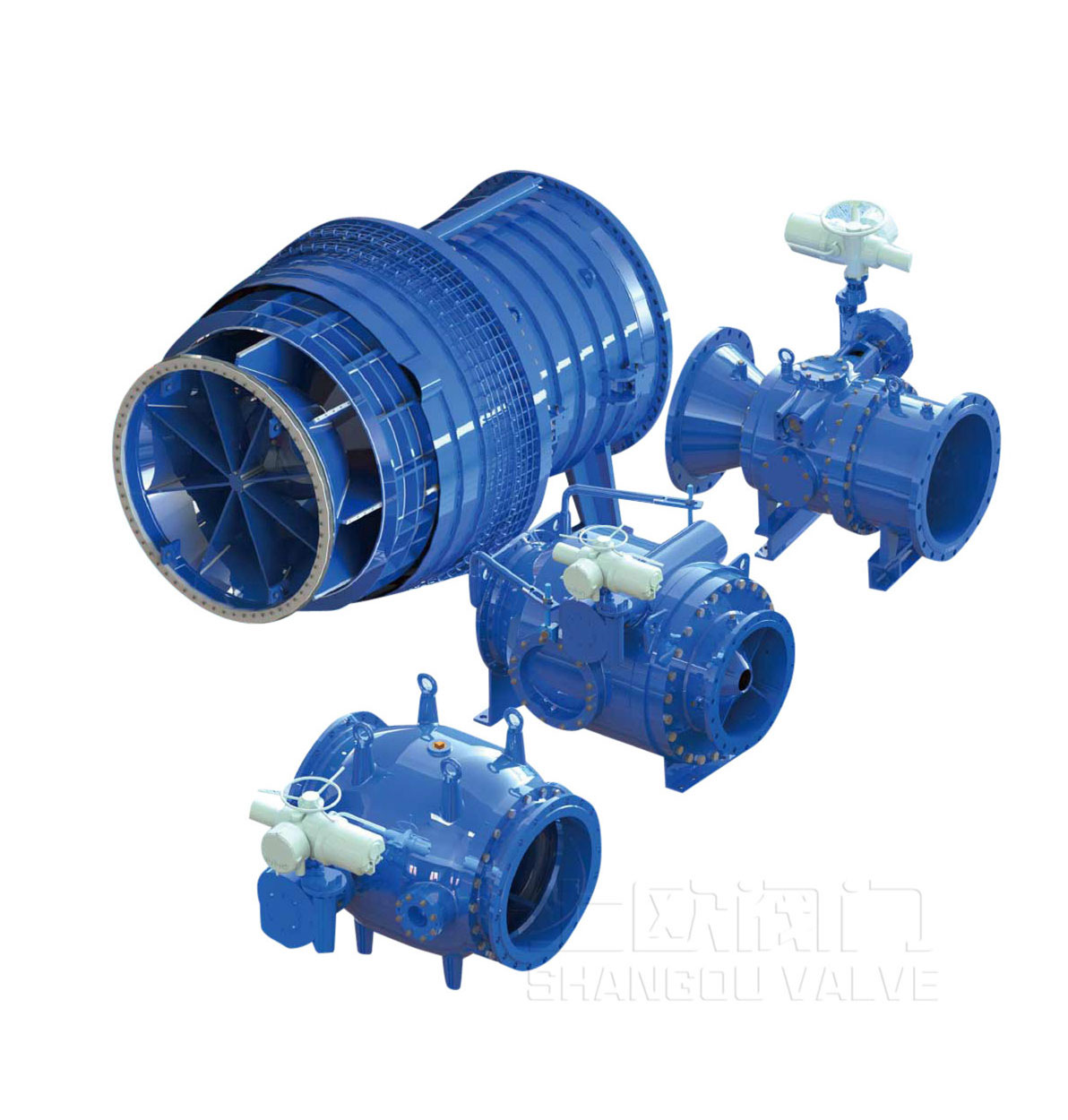
3. Strong wear resistance and erosion resistance: when the valve is opened, the sealing surface of the hemispherical valve core is completely back to the flow channel, which is not scoured; due to the eccentric design, it only contacts with the valve seat at the moment of valve closing, so the wear is small. In addition, the valve core and valve seat sealing surface can adopt various advanced processes such as surfacing nickel base alloy (hardness greater than HRC60), supersonic spraying tungsten cobalt alloy (hardness greater than HRC70) and special hardening materials to form wear-resistant and corrosion-resistant layers, which can effectively adapt to various harsh working conditions and extend the service life of valve. Advanced ceramic lining technology can be used in the flow passage to effectively eliminate the wear of valve body. The valve shaft and bearing are designed with anti sediment design to prevent impurities from scouring and entering.
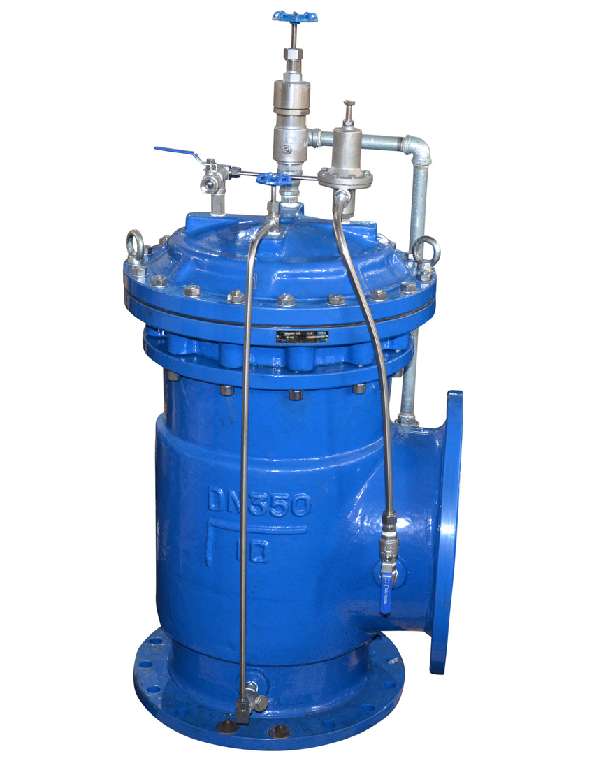
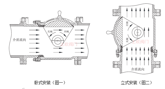
4. No slag accumulation and no water loss: as shown in the figure below, the valve adopts full channel design. When the valve is fully opened, the hemispherical valve core is on one side of the flow channel, which does not occupy the space of the flow channel to hinder the flow of fluid, and is not easy to produce slag accumulation and eddy current. It is especially suitable for "double high" media with high slag content and high flow rate.
5. Long service life of seal: the valve plate sweeps over the valve seat by rotation when closing, and eliminates and rolls the granular impurities. When closing, it can cut off the long strip impurities which are difficult to peel off or hang like an obtuse angle cutting tool, so as to achieve the pure bonding of the sealing pair and effectively extend the service life of the seal.
6. Convenient maintenance: high quality hydraulic and electrical components are adopted and standardized module design is adopted to facilitate operation and maintenance;
| Standard content | Standard number | Standard name |
| Design and manufacturing standards | CJ/T283-2008 | Eccentric hemisphere valve |
| Structural length standard | GB/T12221 | Structural length of metal valve |
| Flange standard | GB/T9113.1-4 | Integral steel pipe flange / customer specified standard |
| GB/T17241.6 | Integral cast iron pipe flange | |
| Accumulator | GB/T2352 | Pressure and volume range and characteristic quantity of isolated gas filled accumulator |
| Inspection and test standards | GB/T13927 | Pressure test for general purpose valves |
| JB/T9092 | Test and inspection of valves | |
| Standard of materials used | GB/T12227 | Technical conditions of ductile iron castings for general purpose valves |
| GB/T12229 | Technical specification of carbon steel castings for general purpose valves | |
| GB/T12230 | Technical requirements of austenitic steel castings for general purpose valves |
Note: other relevant standards and foreign standards can be used. Flange size can be manufactured according to user's requirements, but it should be indicated in the order contract.
| Nominal pressure |
PN |
1.0 |
1.6 |
2.5 |
4.0 |
6.3 |
Mpa |
|
| strength test |
PS |
1.5 |
2.4 |
3.8 |
6.0 |
9.45 |
||
| Sealing test |
P |
1.1 |
1.8 |
2.8 |
4.4 |
6.93 |
||
| Service temperature |
T |
-29-120℃ |
||||||
| Nominal size |
DN200-DN1200 |
|||||||
| Applicable media | ||||||||
|
|
|
|
|
|
|
|
|
|
Special parameters: (the opening and closing time can be set according to the working conditions)
| project | Adjustable range | Factory preset (adjustable) | |
| Valve opening time (adjustable) | second | ||
| Valve closing time (adjustable) | Shut it down |
1.5-25 second |
8second |
| Slow closing |
6-90 second |
20second |
|

1. Through the electrical control valve cabinet, start the water pump. After debugging and setting time, when the water pump reaches the normal speed, the valve will automatically start the hydraulic station under the program control, the pressure oil will enter the rod less cavity of the upper oil chamber of the valve to push the piston to run, and drive the valve plate to open slowly through the valve shaft.
2. When the pump is stopped, the valve acts synchronously, and the pressure oil in the accumulator of the hydraulic control system enters the rod cavity of the oil cylinder through the reversing valve, so that the oil cylinder returns. The valve is closed automatically in two stages. First, the valve is quickly closed by 65 ° to cut off most of the water flow. Then, the cylinder is slowly closed, and the remaining about 25 ° is closed slowly. Part of the reflux medium is discharged to eliminate the water hammer of pump stop, and the impact between the valve plate and the valve body is prevented. Finally, the valve is completely closed. The closing speed and angle can be adjusted on the rear end device of the oil cylinder.
3. In case of sudden power failure or emergency pump shutdown, the valves are automatically closed in two stages of fast and slow closing according to the set procedure to eliminate the harm of water hammer.
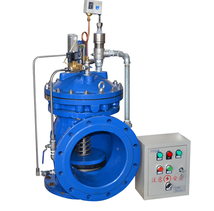
The energy storage hydraulic system is compact in structure and can be placed on the valve connecting frame or near the valve. It is composed of hydraulic station, hydraulic cylinder and electric control box.
1. There are three power sources for the hydraulic system, namely, the oil pump motor group, the hydraulic energy stored in the accumulator and the manual oil pump. The hydraulic energy stored in the accumulator is the main power source. The oil pump unit is responsible for filling the accumulator with liquid, and can also directly drive the valve switch when necessary. The manual oil pump is used to open and close the valve manually when the oil pump motor fails or the accumulator is repaired.
2. In the case of no power or manual operation, manually push the solenoid valve core to make the oil circuit in the corresponding state, or turn the switch on the electric control box in the corresponding state through the self-contained power supply, and shake the manual oil pump to realize the opening and closing of the valve.
3. The working order of the hydraulic control system is: firstly, the hydraulic system starts the oil pump, and the pressure oil enters into the rod less cavity of the oil chamber through the one-way valve and the directional valve to push the piston to run, so as to open the valve and supply oil to the accumulator at the same time. The oil pressure of the accumulator is determined by the pressure controller. The closing of the valve is that the pressure oil in the accumulator enters the rod cavity of the oil cylinder through the reversing valve, which makes the oil cylinder return and quickly close the valve. The opening speed of the valve is regulated by the throttle valve on the manifold block: the valve is closed automatically in two stages, first fast closing 65 ° and then slowly closing, and the remaining 25 ° closing speed and angle are adjusted on the rear end device of the oil cylinder.
1. Oil filter 2, hand pressure oil pump 3, plunger pump 4, motor 5, stop valve 6, check valve 7, relief valve 8, pressure gauge 9, pressure controller 10, accumulator 11, stop valve 12, cartridge valve 13, hydraulic control check valve 14, electromagnetic directional valve 15, three regulation hydraulic cylinder 16, throttle valve 17, electromagnetic directional valve 18, cut-off
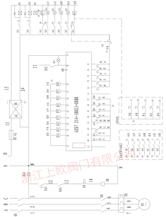
The electrical control box is the control hub of hydraulic station assembly which receives valve status signal and control command and outputs control command and status signal after processing. The main control forms of the electrical control box are universal parts, single chip microcomputer and PLC controller, which can be selected according to the requirements of the system.
a. The general electrical control box is composed of common electrical appliances and electronic components. It is characterized by simple structure, easy assembly, difficult networking and remote control, and low price.
b. Single chip microcomputer electrical control box is composed of single-chip CPU and peripheral components. It is characterized by simple structure, simple intelligence, programmable, network remote control and moderate manufacturing cost.
c. PLC controller type electrical control box is composed of PLC programmable controller and peripheral components. It is characterized by simple structure, intelligence, easy programming, easy realization of network remote control, but the price is high.
| Serial number | Component name | Component model | Company | number | |
|
1 |
air switch |
C65N 3P D16A |
only |
1 |
Schneider Electric or other manufacturers |
|
2 |
air switch |
C65N 2P C6A |
only |
1 |
Schneider Electric or other manufacturers |
|
3 |
Switching power supply (charger) |
S-201-W |
only |
1 |
Taiwan Mingwei or other manufacturers |
|
7 |
AC contactor |
LC1D099MTC |
only |
1 |
Schneider Electric or other manufacturers |
|
8 |
Thermal relay |
LR2D139C |
only | 1 | Schneider Electric or other manufacturers |
|
9 |
PLC |
CPU224 |
platform | Siemens or other manufacturers | |
|
9 |
Intermediate relay |
2C/0 |
only |
9 |
Schneider Electric or other manufacturers |
| 10 | Push button switch (green) |
ZB2 BA3C/BZ95C |
only |
3 |
Schneider Electric or other manufacturers |
|
13 |
Knob switch |
ZB2 BD3C/BZ93C |
only | 3 | Schneider Electric or other manufacturers |
|
14 |
indicator light | only |
8 |
Schneider Electric or other manufacturers | |
|
15 |
terminal |
2.5m2-9m2 |
only |
80 |
Yangzhou Ruiqi or other manufacturers |
| 16 | Axial piston pump |
9MCY14-1B |
only |
1 |
Rexroth or other manufacturers |
| Serial number | Part name | Material Science | Serial number | Part name | Material Science |
|
1 |
valve body | Ductile iron, cast steel, stainless steel, ceramic lining |
7 |
snap ring | copper alloy |
|
2 |
a fastening | stainless steel |
8 |
axle sleeve | copper alloy |
|
3 |
Sealing element Sealing element |
Nitrile rubber, EPDM Sealing element |
9 |
Short axle shaft Sealing element |
stainless steel |
|
4 |
valve seat | Stainless steel, cemented carbide |
10 |
Long axle shaft | stainless steel |
|
5 |
Hemispherical spool | Ductile iron, cast steel and wear-resistant cast steel | 11 | Seal sleeve | Nitrile rubber |
|
6 |
End cap | Gray iron, ductile iron and cast steel | 12 | control device | Hydraulic system |
Table1:
| nominal Diameter |
length | Overall dimension (reference value) | Connection size (standard value) | reference resources weight |
|||||||||||||
|
0.6MPa |
1.OMPa |
||||||||||||||||
| millimeter |
L |
E |
H |
H1 |
A |
B |
M |
K |
P |
n-b |
D |
D1 |
n-d |
D |
D1 |
n-d |
(kg) |
|
200 |
400 |
590 |
520 |
200 |
160 |
180 |
520 |
380 |
650 |
4-16 |
320 |
280 |
8-18 |
340 |
295 |
8-22 |
152 |
|
250 |
450 |
670 |
580 |
235 |
160 |
200 |
520 |
380 |
650 |
4-16 |
375 |
335 |
12-18 |
395 |
350 |
12-22 |
198 |
|
300 |
630 |
770 |
710 |
270 |
220 |
230 |
570 |
496 |
700 |
4-16 |
440 |
395 |
12-22 |
445 |
400 |
12-22 |
280 |
|
350 |
740 |
790 |
770 |
305 |
240 |
260 |
570 |
496 |
700 |
4-20 |
490 |
445 |
12-22 |
505 |
460 |
16-22 |
487 |
|
400 |
840 |
870 |
830 |
335 |
300 |
280 |
602 |
525 |
755 |
4-20 |
540 |
495 |
16-22 |
565 |
515 |
16-26 |
605 |
|
450 |
940 |
950 |
870 |
360 |
320 |
300 |
602 |
525 |
755 |
4-24 |
595 |
550 |
16-22 |
615 |
565 |
20-26 |
806 |
|
500 |
1016 |
1145 |
930 |
390 |
360 |
330 |
602 |
525 |
755 |
4-24 |
645 |
600 |
20-22 |
670 |
620 |
20-26 |
910 |
|
600 |
1140 |
1250 |
1090 |
450 |
450 |
400 |
620 |
556 |
795 |
4-28 |
755 |
705 |
20-26 |
780 |
725 |
20-30 |
1100 |
|
700 |
1320 |
1450 |
1260 |
510 |
480 |
450 |
620 |
556 |
795 |
4-30 |
860 |
810 |
24-26 |
895 |
840 |
24-30 |
2012 |
|
800 |
1500 |
1800 |
1440 |
575 |
620 |
480 |
620 |
556 |
795 |
4-30 |
975 |
920 |
24-30 |
1015 |
950 |
24-33 |
2805 |
|
900 |
1660 |
1940 |
1535 |
630 |
620 |
560 |
620 |
556 |
795 |
4-36 |
1075 |
1020 |
24-30 |
1115 |
1050 |
28-33 |
3950 |
|
1000 |
1850 |
2090 |
1750 |
700 |
700 |
620 |
665 |
576 |
980 |
4-36 |
1175 |
1120 |
28-30 |
1230 |
1160 |
28-36 |
5310 |
|
1200 |
2220 |
2435 |
1960 |
800 |
750 |
720 |
665 |
576 |
980 |
4-42 |
1405 |
1340 |
32-33 |
1455 |
1380 |
32-39 |
6230 |
|
1400 |
2580 |
2860 |
2250 |
900 |
850 |
820 |
665 |
576 |
980 |
4-46 |
1630 |
1560 |
36-36 |
1675 |
1590 |
36-42 |
7830 |
|
1600 |
2960 |
3210 |
2500 |
1020 |
1100 |
960 |
682 |
622 |
1310 |
4-46 |
1830 |
1760 |
40-36 |
1915 |
1820 |
40-48 |
9150 |
|
1800 |
3300 |
3480 |
2820 |
1175 |
1300 |
1060 |
682 |
622 |
1310 |
4-58 |
2045 |
1970 |
44-39 |
2115 |
2020 |
44-48 |
12600 |
|
2000 |
3700 |
3780 |
3150 |
1250 |
1500 |
1160 |
682 |
622 |
1310 |
4-58 |
2265 |
2180 |
48-42 |
2325 |
2230 |
48-48 |
19800 |
|
2200 |
4070 |
4220 |
3500 |
1320 |
1800 |
1300 |
1000 |
920 |
1820 |
4-68 |
2475 |
2390 |
52-42 |
2560 |
2440 |
52-62 |
24000 |
|
2400 |
4500 |
4560 |
3800 |
1430 |
2000 |
1400 |
1000 |
920 |
1820 |
4-68 |
2685 |
2600 |
56-42 |
2760 |
2650 |
56-56 |
35000 |
Table2:
| nominal Diameter |
length | Overall dimension (reference value) | Connection size (standard value) | reference resources weight |
|||||||||||||
|
2.5MPa |
|||||||||||||||||
| millimeter |
L |
E |
H |
HI |
A |
B |
M |
K |
P |
n-b |
D |
D1 |
n-d |
D |
D1 |
n-d |
(kg) |
|
200 |
400 |
590 |
520 |
200 |
160 |
180 |
520 |
380 |
650 |
4-16 |
340 |
295 |
12-22 |
360 |
310 |
12-26 |
152 |
|
250 |
450 |
670 |
580 |
235 |
160 |
200 |
520 |
380 |
650 |
4-16 |
405 |
355 |
12-26 |
425 |
370 |
12-30 |
198 |
|
300 |
630 |
770 |
710 |
270 |
220 |
230 |
570 |
496 |
700 |
4-16 |
460 |
410 |
12-26 |
485 |
430 |
16-30 |
280 |
|
350 |
740 |
790 |
770 |
305 |
240 |
260 |
570 |
496 |
700 |
4-20 |
520 |
470 |
16-26 |
555 |
490 |
16-33 |
487 |
|
400 |
840 |
870 |
830 |
335 |
300 |
280 |
602 |
525 |
755 |
4-20 |
580 |
525 |
16-30 |
620 |
550 |
16-36 |
605 |
|
450 |
940 |
950 |
870 |
360 |
320 |
300 |
602 |
525 |
755 |
4-24 |
640 |
585 |
20-30 |
670 |
600 |
20-36 |
806 |
|
500 |
1016 |
1145 |
930 |
390 |
360 |
330 |
602 |
525 |
755 |
4-24 |
715 |
650 |
20-33 |
730 |
660 |
20-36 |
910 |
|
600 |
1140 |
1250 |
1090 |
450 |
450 |
400 |
620 |
556 |
795 |
4-28 |
840 |
770 |
20-36 |
845 |
770 |
20-39 |
1100 |
|
700 |
1320 |
1450 |
1260 |
510 |
480 |
450 |
620 |
556 |
795 |
4-30 |
910 |
840 |
24-36 |
960 |
875 |
24-42 |
2012 |
|
800 |
1500 |
1800 |
1440 |
575 |
620 |
480 |
620 |
556 |
795 |
4-30 |
1025 |
950 |
24-39 |
1085 |
990 |
24-48 |
2805 |
|
900 |
1660 |
1940 |
1535 |
630 |
620 |
560 |
620 |
556 |
795 |
4-36 |
1125 |
1050 |
28-39 |
1185 |
1090 |
28-48 |
3950 |
|
1000 |
1850 |
2090 |
1750 |
700 |
700 |
620 |
665 |
576 |
980 |
4-36 |
1255 |
1170 |
28-42 |
1320 |
1210 |
28-55 |
5310 |
|
1200 |
2220 |
2435 |
1960 |
800 |
750 |
720 |
665 |
576 |
980 |
4-42 |
1485 |
1390 |
32-48 |
1530 |
1420 |
32-55 |
6230 |
Table 3:
| nominal Diameter |
length | Overall dimension (reference value) | Connection size (standard value) | reference resources Weight |
|||||||||||||
|
4.0MPa |
6.3MPa |
||||||||||||||||
| millimeter |
L |
E |
H |
H1 |
A |
B |
M |
K |
P |
n-b |
D |
D1 |
n-d |
D |
D1 |
n-d |
(kg) |
|
200 |
400 |
375 |
375 |
375 |
320 |
375 |
320 |
375 |
650 |
4-20 |
375 |
320 |
12-30 |
415 |
345 |
12-36 |
280 |
|
250 |
450 |
450 |
450 |
450 |
385 |
450 |
385 |
450 |
650 |
4-20 |
450 |
385 |
12-33 |
470 |
400 |
12-36 |
487 |
|
300 |
630 |
515 |
515 |
515 |
450 |
515 |
450 |
515 |
700 |
4-24 |
515 |
450 |
16-33 |
530 |
460 |
16-36 |
605 |
|
350 |
740 |
580 |
580 |
580 |
510 |
580 |
510 |
580 |
700 |
4-24 |
580 |
510 |
16-36 |
600 |
525 |
16-39 |
806 |
|
400 |
840 |
660 |
660 |
660 |
585 |
660 |
585 |
660 |
755 |
4-28 |
660 |
585 |
16-39 |
670 |
585 |
16-42 |
910 |
|
450 |
940 |
685 |
685 |
685 |
610 |
685 |
610 |
685 |
755 |
4-30 |
685 |
610 |
20-39 |
/ |
/ |
/ |
1100 |
|
500 |
1016 |
755 |
755 |
755 |
670 |
755 |
670 |
755 |
755 |
4-30 |
755 |
670 |
20-42 |
/ |
/ |
/ |
2012 |
|
600 |
1140 |
890 |
890 |
890 |
795 |
890 |
795 |
890 |
795 |
4-36 |
890 |
795 |
20-48 |
/ |
/ |
/ |
2805 |
|
700 |
1320 |
995 |
995 |
995 |
900 |
995 |
900 |
995 |
795 |
4-36 |
995 |
900 |
24-48 |
/ |
/ |
/ |
3950 |
|
800 |
1500 |
1140 |
1140 |
1140 |
1030 |
1140 |
1030 |
1140 |
795 |
4-42 |
1140 |
1030 |
24-56 |
/ |
/ |
/ |
5310 |
|
900 |
1660 |
1250 |
1250 |
1250 |
1140 |
1250 |
1140 |
1250 |
795 |
4-46 |
1250 |
1140 |
28-56 |
/ |
/ |
/ |
6230 |
|
1000 |
1850 |
1360 |
1360 |
1360 |
1250 |
1360 |
1250 |
1360 |
980 |
4-46 |
1360 |
1250 |
28-56 |
/ |
/ |
/ |
7830 |
Note: due to product improvement, there may be some differences between the material object and the publicity materials. We reserve the right to interpret the above data. Please contact the technical department of our company for specific parameters.
Precautions for installation and use
1. Valves and hydraulic devices shall be placed in a ventilated and dry room, and shall not be stacked or stored in the open air to prevent damage and corrosion;
2. During long-term storage or maintenance, the two valves should be closed and the valve should be in the closed state to prevent foreign matters from entering the cavity and losing the sealing surface;
3. Before installation, the valve should be carefully verified whether the service condition is consistent with the performance specification, and the valve cavity should be cleaned to keep the sealing surface clean;
4. The hydraulic system should be regularly overhauled, filtered or replaced with hydraulic oil, and the oil tank should be cleaned.
5. The valve is one-way use, installation must be in accordance with the arrow direction of the valve, reverse installation is strictly prohibited.
6. Please pay attention to protect the pressure gauge and bypass pipe during hoisting and installation.
7. The valve is closed for a long time when it is used. It is better to open the water regularly to flush the slag slurry. In general, it is necessary to send water for flushing at least once after opening.
8. Hydraulic oil should be selected according to the requirements, yb-n32 or yb-n46 anti-wear hydraulic oil can be selected in general area, yc-n32 or yc-n46 low-temperature hydraulic oil can be selected in cold area. (low temperature hydraulic oil can be used in all seasons)
9. Local or remote control can be selected according to the working conditions. When the transfer switch of the local electric control box is switched to the stop position, the buttons on the electric control box will not work.
| Serial number | Part name | Material Science | Serial number | Part name | Material Science |
|
1 |
valve body | Ductile iron, cast steel, stainless steel, ceramic lining |
7 |
snap ring | copper alloy |
|
2 |
a fastening | stainless steel |
8 |
axle sleeve | copper alloy |
|
3 |
Sealing element | Nitrile rubber, EPDM |
9 |
Short axle shaft | stainless steel |
|
4 |
valve seat | Stainless steel, cemented carbide |
10 |
Long axle shaft | stainless steel |
|
5 |
Hemispherical spool | Ductile iron, cast steel and wear-resistant cast steel |
11 |
Seal sleeve | Nitrile rubber |
|
6 |
End cap | Gray iron, ductile iron and cast steel |
12 |
control device | Hydraulic system |
Table 1:
| nominal Diameter |
length |
Overall dimension (reference value) |
Connection size (standard value) | reference resources weight |
|||||||||||||
|
0.6MPa |
1.OMPa |
||||||||||||||||
| millimeter |
L |
E |
H |
H1 |
A |
B |
M |
K |
P |
n-b |
D |
D1 |
n-d |
D |
D1 |
n-d |
(kg) |
|
200 |
400 |
590 |
520 |
200 |
160 |
180 |
520 |
380 |
650 |
4-16 |
320 |
280 |
8-18 |
340 |
295 |
8-22 |
152 |
|
250 |
450 |
670 |
580 |
235 |
160 |
200 |
520 |
380 |
650 |
4-16 |
375 |
335 |
12-18 |
395 |
350 |
12-22 |
198 |
|
300 |
630 |
770 |
710 |
270 |
220 |
230 |
570 |
496 |
700 |
4-16 |
440 |
395 |
12-22 |
445 |
400 |
12-22 |
280 |
|
350 |
740 |
790 |
770 |
305 |
240 |
260 |
570 |
496 |
700 |
4-20 |
490 |
445 |
12-22 |
505 |
460 |
16-22 |
487 |
|
400 |
840 |
870 |
830 |
335 |
300 |
280 |
602 |
525 |
755 |
4-20 |
540 |
495 |
16-22 |
565 |
515 |
16-26 |
605 |
|
450 |
940 |
950 |
870 |
360 |
320 |
300 |
602 |
525 |
755 |
4-24 |
595 |
550 |
16-22 |
615 |
565 |
20-26 |
806 |
|
500 |
1016 |
1145 |
930 |
390 |
360 |
330 |
602 |
525 |
755 |
4-24 |
645 |
600 |
20-22 |
670 |
620 |
20-26 |
910 |
|
600 |
1140 |
1250 |
1090 |
450 |
450 |
400 |
620 |
556 |
795 |
4-28 |
755 |
705 |
20-26 |
780 |
725 |
20-30 |
1100 |
|
700 |
1320 |
1450 |
1260 |
510 |
480 |
450 |
620 |
556 |
795 |
4-30 |
860 |
810 |
24-26 |
895 |
840 |
24-30 |
2012 |
|
800 |
1500 |
1800 |
1440 |
575 |
620 |
480 |
620 |
556 |
795 |
4-30 |
975 |
920 |
24-30 |
1015 |
950 |
24-33 |
2805 |
|
900 |
1660 |
1940 |
1535 |
630 |
620 |
560 |
620 |
556 |
795 |
4-36 |
1075 |
1020 |
24-30 |
1115 |
1050 |
28-33 |
3950 |
|
1000 |
1850 |
2090 |
1750 |
700 |
700 |
620 |
665 |
576 |
980 |
4-36 |
1175 |
1120 |
28-30 |
1230 |
1160 |
28-36 |
5310 |
|
1200 |
2220 |
2435 |
1960 |
800 |
750 |
720 |
665 |
576 |
980 |
4-42 |
1405 |
1340 |
32-33 |
1455 |
1380 |
32-39 |
6230 |
|
1400 |
2580 |
2860 |
2250 |
900 |
850 |
820 |
665 |
576 |
980 |
4-46 |
1630 |
1560 |
36-36 |
1675 |
1590 |
36-42 |
7830 |
|
1600 |
2960 |
3210 |
2500 |
1020 |
1100 |
960 |
682 |
622 |
1310 |
4-46 |
1830 |
1760 |
40-36 |
1915 |
1820 |
40-48 |
9150 |
|
1800 |
3300 |
3480 |
2820 |
1175 |
1300 |
1060 |
682 |
622 |
1310 |
4-58 |
2045 |
1970 |
44-39 |
2115 |
2020 |
44-48 |
12600 |
|
2000 |
3700 |
3780 |
3150 |
1250 |
1500 |
1160 |
682 |
622 |
1310 |
4-58 |
2265 |
2180 |
48-42 |
2325 |
2230 |
48-48 |
19800 |
|
2200 |
4070 |
4220 |
3500 |
1320 |
1800 |
1300 |
1000 |
920 |
1820 |
4-68 |
2475 |
2390 |
52-42 |
2560 |
2440 |
52-62 |
24000 |
|
2400 |
4500 |
4560 |
3800 |
1430 |
2000 |
1400 |
1000 |
920 |
1820 |
4-68 |
2685 |
2600 |
56-42 |
2760 |
2650 |
56-56 |
35000 |
Table 2:
| nominal Diameter |
length | Overall dimension (reference value) | Connection size (standard value) | reference resources weight |
|||||||||||||
|
1.6MPa |
2.5MPa |
||||||||||||||||
| millimeter |
L |
E |
H |
HI |
A |
B |
M |
K |
P |
n-b |
D |
D1 |
n-d |
D |
D1 |
n-d |
(kg) |
|
200 |
400 |
590 |
520 |
200 |
160 |
180 |
520 |
380 |
650 |
4-16 |
340 |
295 |
12-22 |
360 |
310 |
12-26 |
152 |
|
250 |
450 |
670 |
580 |
235 |
160 |
200 |
520 |
380 |
650 |
4-16 |
405 |
355 |
12-26 |
425 |
370 |
12-30 |
198 |
|
300 |
630 |
770 |
710 |
270 |
220 |
230 |
570 |
496 |
700 |
4-16 |
460 |
410 |
12-26 |
485 |
430 |
16-30 |
280 |
|
350 |
740 |
790 |
770 |
305 |
240 |
260 |
570 |
496 |
700 |
4-20 |
520 |
470 |
16-26 |
555 |
490 |
16-33 |
487 |
|
400 |
840 |
870 |
830 |
335 |
300 |
280 |
602 |
525 |
755 |
4-20 |
580 |
525 |
16-30 |
620 |
550 |
16-36 |
605 |
|
450 |
940 |
950 |
870 |
360 |
320 |
300 |
602 |
525 |
755 |
4-24 |
640 |
585 |
20-30 |
670 |
600 |
20-36 |
806 |
|
500 |
1016 |
1145 |
930 |
390 |
360 |
330 |
602 |
525 |
755 |
4-24 |
715 |
650 |
20-33 |
730 |
660 |
20-36 |
910 |
|
600 |
1140 |
1250 |
1090 |
450 |
450 |
400 |
620 |
556 |
795 |
4-28 |
840 |
770 |
20-36 |
845 |
770 |
20-39 |
1100 |
|
700 |
1320 |
1450 |
1260 |
510 |
480 |
450 |
620 |
556 |
795 |
4-30 |
910 |
840 |
24-36 |
960 |
875 |
24-42 |
2012 |
|
800 |
1500 |
1800 |
1440 |
575 |
620 |
480 |
620 |
556 |
795 |
4-30 |
1025 |
950 |
24-39 |
1085 |
990 |
24-48 |
2805 |
|
900 |
1660 |
1940 |
1535 |
630 |
620 |
560 |
620 |
556 |
795 |
4-36 |
1125 |
1050 |
28-39 |
1185 |
1090 |
28-48 |
3950 |
|
1000 |
1850 |
2090 |
1750 |
700 |
700 |
620 |
665 |
576 |
980 |
4-36 |
1255 |
1170 |
28-42 |
1320 |
1210 |
28-55 |
5310 |
|
1200 |
2220 |
2435 |
1960 |
800 |
750 |
720 |
665 |
576 |
980 |
4-42 |
1485 |
1390 |
32-48 |
1530 |
1420 |
32-55 |
6230 |
Table 3
nominal
Diameter
| length | Overall dimension (reference value) | Connection size (standard value) | reference resources Weight |
||||||||||||||
|
4.0MPa |
6.3MPa |
||||||||||||||||
| millimeter |
E |
H |
H1 |
A |
B |
M |
K |
P |
n-b |
D |
D1 |
n-d |
D |
D1 |
n-d |
(kg) |
|
|
200 |
400 |
375 |
375 |
375 |
320 |
375 |
320 |
375 |
650 |
4-20 |
375 |
320 |
12-30 |
415 |
345 |
12-36 |
280 |
|
250 |
450 |
450 |
450 |
450 |
385 |
450 |
385 |
450 |
650 |
4-20 |
450 |
385 |
12-33 |
470 |
400 |
12-36 |
487 |
|
300 |
630 |
515 |
515 |
515 |
450 |
515 |
450 |
515 |
700 |
4-24 |
515 |
450 |
16-33 |
530 |
460 |
16-36 |
605 |
|
350 |
740 |
580 |
580 |
580 |
510 |
580 |
510 |
580 |
700 |
4-24 |
580 |
510 |
16-36 |
600 |
525 |
16-39 |
806 |
|
400 |
840 |
660 |
660 |
660 |
585 |
660 |
585 |
660 |
755 |
4-28 |
660 |
585 |
16-39 |
670 |
585 |
16-42 |
910 |
|
450 |
940 |
685 |
685 |
685 |
610 |
685 |
610 |
685 |
755 |
4-30 |
685 |
610 |
20-39 |
/ |
/ |
/ |
1100 |
|
500 |
1016 |
755 |
755 |
755 |
670 |
755 |
670 |
755 |
755 |
4-30 |
755 |
670 |
20-42 |
/ |
/ |
/ |
2012 |
|
600 |
1140 |
890 |
890 |
890 |
795 |
890 |
795 |
890 |
795 |
4-36 |
890 |
795 |
20-48 |
/ |
/ |
/ |
2805 |
|
700 |
1320 |
995 |
995 |
995 |
900 |
995 |
900 |
995 |
795 |
4-36 |
995 |
900 |
24-48 |
/ |
/ |
/ |
3950 |
|
800 |
1500 |
1140 |
1140 |
1140 |
1030 |
1140 |
1030 |
1140 |
795 |
4-42 |
1140 |
1030 |
24-56 |
/ |
/ |
/ |
5310 |
|
900 |
1660 |
1250 |
1250 |
1250 |
1140 |
1250 |
1140 |
1250 |
795 |
4-46 |
1250 |
1140 |
28-56 |
/ |
/ |
/ |
6230 |
|
1000 |
1850 |
1360 |
1360 |
1360 |
1250 |
1360 |
1250 |
1360 |
980 |
4-46 |
1360 |
1250 |
28-56 |
/ |
/ |
/ |
7830 |
Note: due to product improvement, there may be some differences between the material object and the publicity materials. We reserve the right to interpret the above data. Please contact the technical department of our company for specific parameters.
1. Valves and hydraulic devices shall be placed in a ventilated and dry room, and shall not be stacked or stored in the open air to prevent damage and corrosion;
2. During long-term storage or maintenance, the two valves should be closed and the valve should be in the closed state to prevent foreign matters from entering the cavity and losing the sealing surface;
3. Before installation, the valve should be carefully verified whether the service condition is consistent with the performance specification, and the valve cavity should be cleaned to keep the sealing surface clean;
4. The hydraulic system should be regularly overhauled, filtered or replaced with hydraulic oil, and the oil tank should be cleaned.
5. The valve is one-way use, installation must be in accordance with the arrow direction of the valve, reverse installation is strictly prohibited.
6. Please pay attention to protect the pressure gauge and bypass pipe during hoisting and installation.
7. The valve is closed for a long time when it is used. It is better to open the water regularly to flush the slag slurry. In general, it is necessary to send water for flushing at least once after opening.
8. Hydraulic oil should be selected according to the requirements, yb-n32 or yb-n46 anti-wear hydraulic oil can be selected in general area, yc-n32 or yc-n46 low-temperature hydraulic oil can be selected in cold area. (low temperature hydraulic oil can be used in all seasons)
9. Local or remote control can be selected according to the working conditions. When the transfer switch of the local electric control box is switched to the stop position, the buttons on the electric control box will not work.
自动水力控制阀进出口压力推荐及防.....
Maintenance Manu.....
V-type ball valve is a kind of.....蝶阀常见的试验和安装及故障排除方.....
1、本产品无论是手动、气动、液动、电动各部件在出厂前均经严.....管力阀八大技术特点分析
管力阀八大技术特点分析旋球阀产品概述
旋球阀结合球阀的优越密 封性能与蝶阀的优势结构性能研发而成,.....常用球阀等产品所执行的国家标准解.....
《通用阀门法兰和对焊连接钢制球阀》GB/T12237-89 .....管力阀是一种什么样的阀门
管力阀是我公司历时五年研发的zui新水泵出口控制阀,是继老.....调流调压阀焊接技术要求
调流调压阀是一种多功能活塞式调节阀、该产品有活塞式、套筒式、.....Fast Navigation
Product Line
Recommended Products
Technical Support
Copyright:Shangou Valve Co.,Ltd Record No:; Sitemap
Friendship Links: SenAu Product website