0577-67975099
 QQ
QQ WeChat
 邮箱
邮箱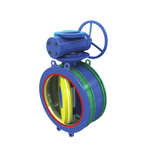
Telephone:
0577-67975099
 Location:Home > Product Center > control valve > BFDKMulti function axial flow control valve
 Telephone:
0577-67975099
Telephone:
0577-67975099

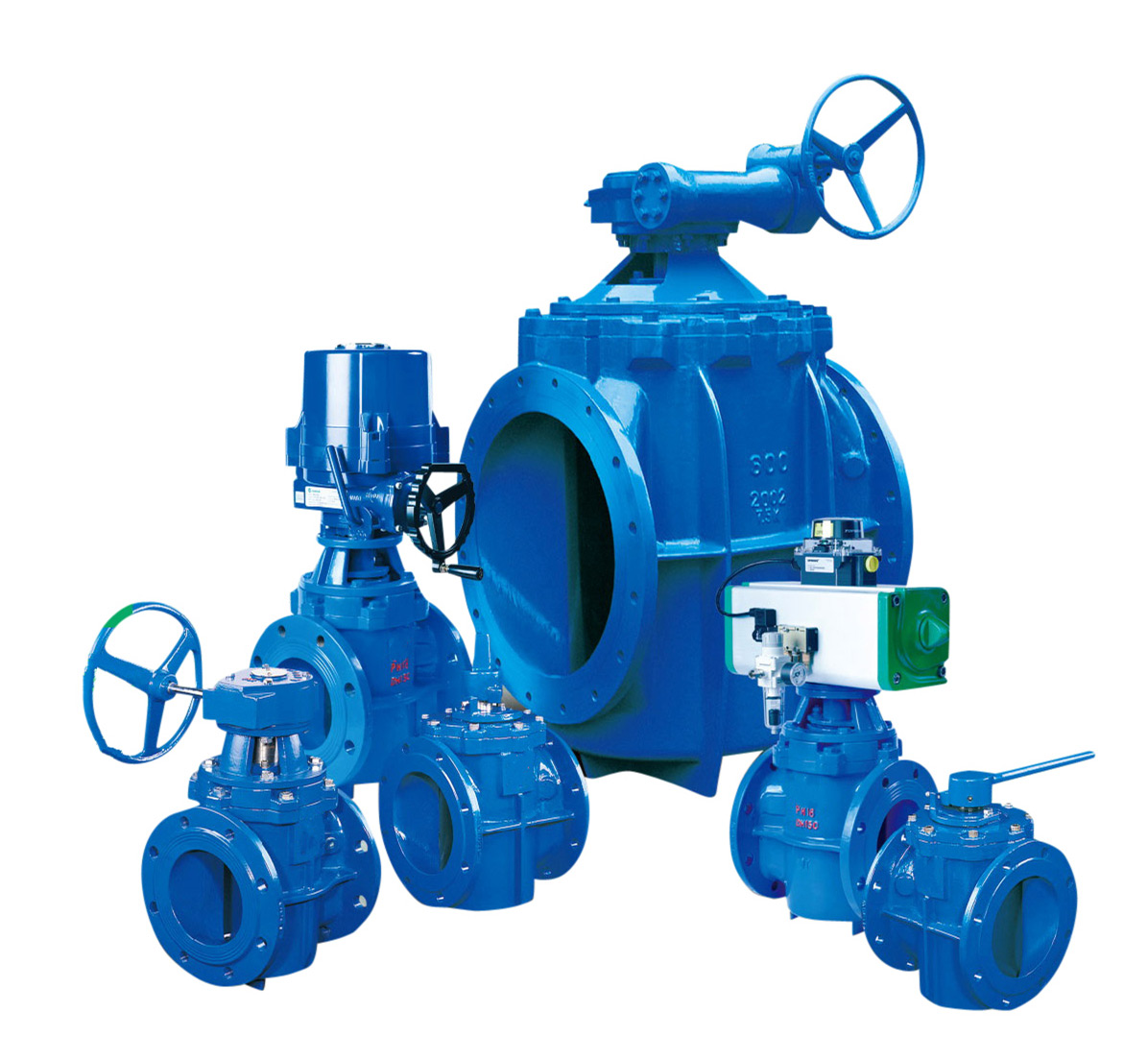
Multifunctional axial flow control valve, also known as piston valve, is the latest product developed by our company on the basis of absorbing foreign technology. It has many functions, such as flow control, decompression and pressure stabilization control, pressure relief and pressure holding control, venting and energy dissipation. The valve has novel structure, advanced performance and reliable operation. It can be widely used in various water supply and drainage systems of water conservancy and hydropower, metallurgy, petrochemical, water department, municipal administration, environmental protection and other industries, as well as oil and gas medium systems. (hereinafter referred to as control valve)
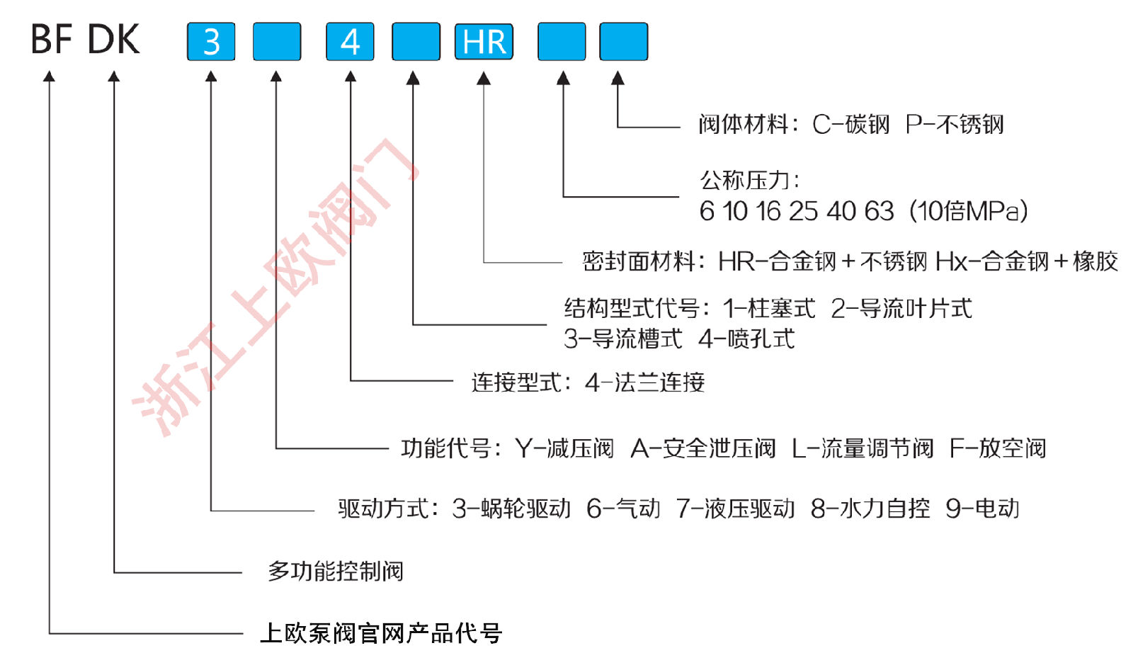
Model example:
Bfdk9l41hr-10c plug flange connection hard seal cast steel electric flow control multi-function axial flow control valve
Bfdk8a44hr-16c spray hole flange connection hard seal cast steel hydraulic automatic safety relief multi-functional axial flow control valve
Performance guarantee value
Technical parameters (1MPa = 10kgf / cm2)
| project | parameter |
|
Nominal pressure(MPa) |
0.6-6.3MPa |
| Leakage | |
|
Applicable temperature(℃) |
-29~120℃ |
| Applicable media | Water, air, natural gas, gas, etc |
technical parameter(1MPa=10kgf/cm2)
| project | parameter |
|
Nominal pressure(MPa) |
0.6-6.3MPa |
| Leakage | Comply with GB / t13927 standard |
|
Applicable temperature(℃) |
-29~120℃ |
| Applicable media | Water, air, natural gas, gas, etc |
Parameter summary table of multi function axial flow control valve
| Serial number item Set pressure (H / relief condition) |
parameter Set pressure (H / relief condition) |
remarks Set pressure (H / relief condition) |
||
|
1 |
Valve name Set pressure (H / relief condition) |
control valve Set pressure (H / relief condition) |
Can be equipped with control box (decompression / relief / flow regulation) Set pressure (H / relief condition) |
|
|
2 |
Nominal pressure Set pressure (H / relief condition) |
PN |
||
|
3 |
Shell test pressure Set pressure (H / relief condition) |
|||
|
4 |
Sealing test pressure Set pressure (H / relief condition) |
1.1PN |
||
|
7 |
Set pressure (H / relief condition) Set pressure (H / relief condition) |
Nominal pressure Set pressure (H / relief condition) |
Adjustment range Set pressure (H / relief condition) |
It can be set according to the working conditions |
|
1.0 MPa |
0.05-0.9 MPa |
|||
|
1.6 MPa |
0.05-1.4 MPa |
|||
|
2.5 MPa |
0.05 -2.3 MPa |
|||
|
4.0 MPa |
01-3.8 MPa |
|||
|
6.3 MPa |
0.1-6.0 MPa |
|||
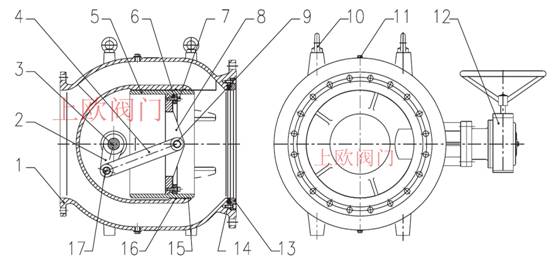
Fig. 1 valve structure diagram
| Serial number | name | Material Science | Serial number | name | Material Science |
| 1 | valve body | Ductile iron QT450-10 / cast steel WCB / stainless steel |
10 |
rings |
35# |
|
2 |
crank |
Stainless copper2Crl3 |
11 |
Plug |
stainless steelA2-70 |
|
3 |
Drive shaft |
stainless steel2Crl3 |
12 |
Executive Agency | Handwheel / intelligent electric installation |
|
4 |
connecting rod |
stainless steel2Crl3 |
13 |
Sealing ring |
stainless steel2Cr13 |
|
5 |
Sleeve |
stainless steel304/316 |
14 |
Sealing element | Butadiene rubber |
|
6 |
Sleeve gland |
stainless steel2Crl3 |
15 |
Sleeve guide |
Sleeve guide ZCuAll0Fe3 |
|
7 |
a fastening |
stainless steelA2-70 |
16 |
Drive bearing Ink seal |
Butadiene rubber Ink seal |
|
8 |
Crankshaft support |
stainless steel2Crl3 |
17 |
Drive pin shaft Ink seal |
stainless steel2Cr13 |
|
9 |
Drive bearing |
Aluminum bronze ZCuAl10Fe3 |
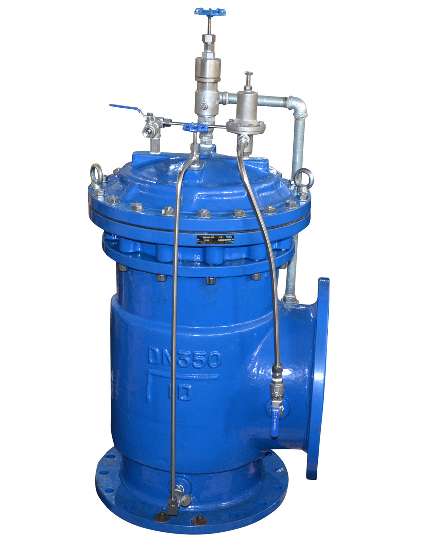
Multi function axial flow control valve is composed of valve body, stem, crank and sleeve. The deflector made of stainless steel is fixed in the middle chamber of the valve body. The deflector has guide groove type, guide vane type and spray hole type. The sleeve looper is in the valve body cavity and connected with the valve stem. The position of the sleeve is controlled by the external control parts to adjust the flow area of the valve. The external control components can be manual, electric, pneumatic and hydraulic according to the working conditions.
Set pressure
Structural form and material in (H / h pressure reducing condition)
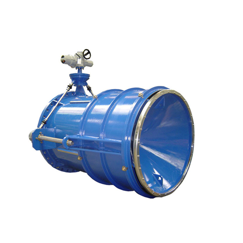
Fig. 2 guide vane type
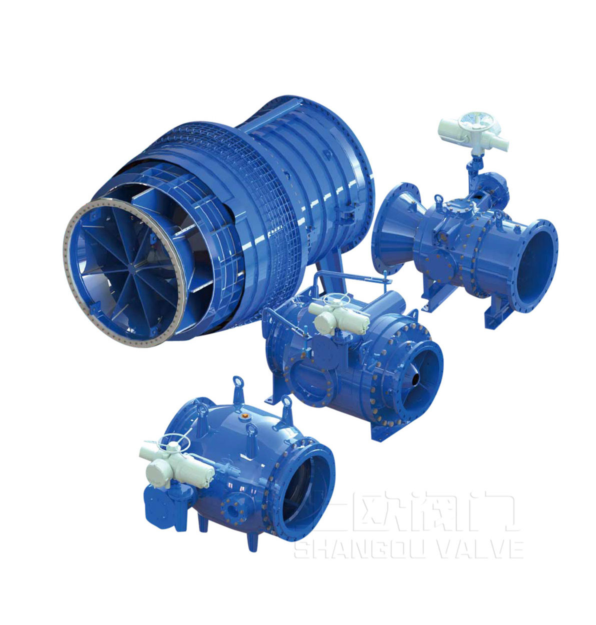
The multi-functional axial flow control valve has the following four main forms, and its structure and application range are as follows:
Set pressure
Structural form and material in (H / h pressure reducing condition)

1. Plunger type structure can be widely used in water, oil and gas systems, with simple structure, reliable operation, small head loss and low requirements for medium cleanliness, which is the most commonly used form.
2. Guide vane type is suitable for large pressure difference, gas-liquid mixing and other working conditions, stable operation and low cavitation.
3. The structure of diversion groove has superior regulation performance, which can be used in high pressure differential system and working conditions with suspended particles and other impurities, and has good cavitation resistance.
4. The results show that the orifice structure has the best adjustability, and the effect of flow regulation and pressure reduction is the best under the condition of ultra-high pressure difference.
Set pressure
Structural form and material in (H / h pressure reducing condition)
The sleeve is placed on the inner cavity of the valve body and guided by the guide rail. The water flows from the outside of the guide device and forms multiple streams of water through the jet hole on the deflector, which produces collision in the middle chamber of the valve body to achieve the effect of energy dissipation. The throttling occurs between the sleeve edge and the orifice of the deflector. Due to the high flow velocity in the hole, the material selected for the deflector is highly wear-resistant and corrosion-resistant. At the same time, due to the collision, the middle chamber of the valve channel is effectively reduced The influence of cavitation and erosion on valve body can improve the service life of valve. The main seal ring is located at the front end of the deflector, and the sleeve is guided in the full stroke. When it is pushed through the main seal ring to the fully closed position, the differential pressure between the front and rear of the valve forces the main seal ring to cling to the outer wall of the sleeve to cut off. The sleeve moves back and forth in the cavity of the valve body through the guide of the connecting rod, and the valve rod is driven by the crank and connecting rod. When the actuator drives the valve stem to rotate against the clock, the sleeve moves backward to open the valve; when the actuator drives the valve stem to rotate clockwise, the sleeve moves forward to close the valve.
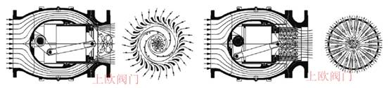
Fig. 4 Schematic diagram of valve energy dissipation
Axial symmetrical flow passage: the valve body adopts axial symmetrical flow passage, and the medium flows into the valve through streamline inner cavity. The shape of flow passage at any position in the valve is circular. Compared with the traditional valve, the flow channel of sleeve valve is smooth, and the fluid has no sharp turning under any opening, which avoids unnecessary change of flow direction, significantly reduces noise and turbulence trend, and reduces valve cavitation.
Pressure balance: because the multi-functional axial flow control valve adopts pressure balance sleeve, the axial force of operating sleeve has nothing to do with the pressure difference at both ends of the valve, so the purpose of quick action can be achieved by using smaller actuator (the opening and closing torque is only 1 / 3-1 / 5 of that of ordinary gate valve, butterfly valve and other transmission valves).
Good regulation effect: almost digital control, through changing the number of flow holes to achieve the change of flow area, with good linear regulation characteristics.
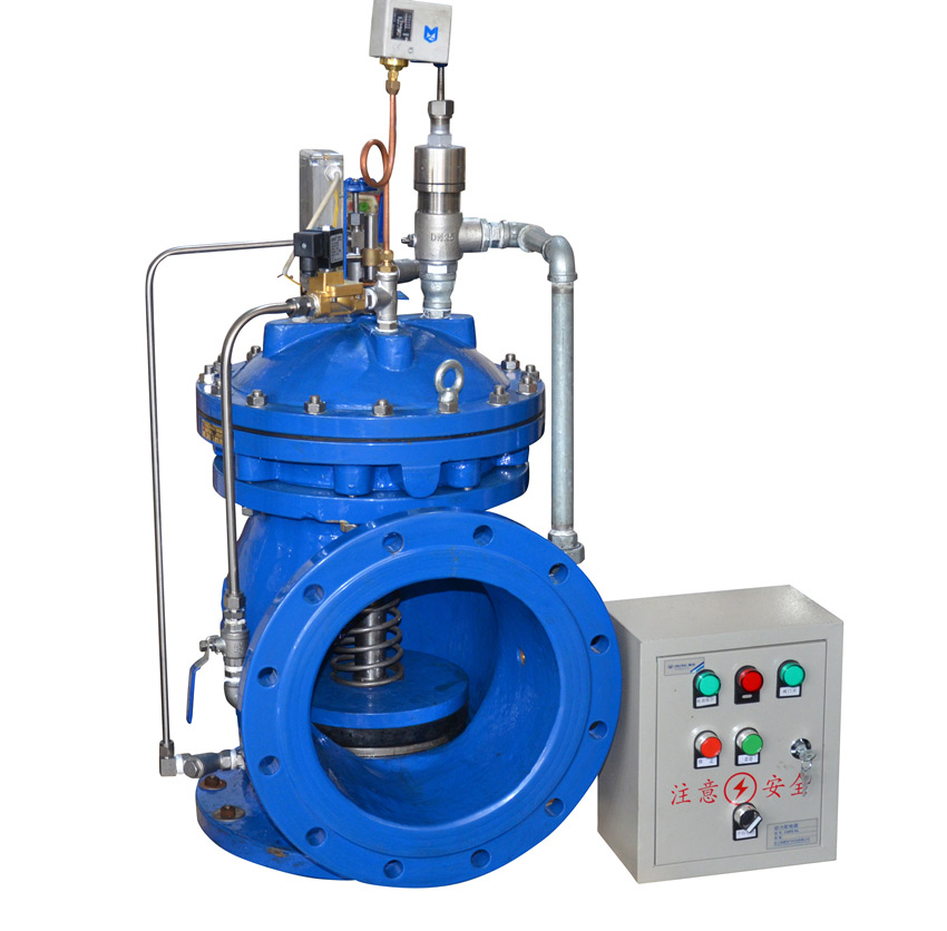
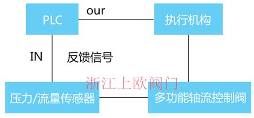
1. The pressure sensor outputs 4-20mA DC signal to calibrate the corresponding minimum pressure value and maximum pressure value.
2. The output feedback signal of pressure sensor is sent to PLC for processing. After comparing the preset values of PLC, the corresponding control signal is output to the electric actuator, and the valve is driven to the corresponding position (valve opening).
3. PLC is responsible for opening reservation, feedback signal comparison and control; output work, the electric actuator is responsible for driving the valve to the specified position according to the PLC command, the control precision is set by PLC, this method is closed-loop control, stable and reliable.
4. The electric actuator adopts intelligent type, which has many functions such as stroke protection, torque protection, phase failure alarm, etc.
In order to ensure your requirements, please specify the name, model and specification, maximum working pressure, temperature, medium and special requirements. According to your requirements, our company can also provide supporting flange, bolt, expansion joint, butterfly valve maintenance, etc.
Valve structure size

PN1.0-PN2.5MPaTable of external dimensions and connection dimensions of multifunctional axial flow control valve
| nominal Diameter |
Overall dimension (standard value) | Connection size (standard value) | ||||||||||||||
|
PN1.0 MPa |
PN1.6 MPa |
PN2.5 MPa |
||||||||||||||
|
L |
B |
H |
H1 |
D |
D1 |
n-Фd |
b |
D |
D1 |
n-Фd |
b |
D |
D1 |
n-Фd |
b |
|
|
100 |
325 |
210 |
160 |
80 |
220 |
180 |
8-Ф18 |
22 |
220 |
180 |
8-Ф18 |
22 |
235 |
190 |
8-Ф22 |
24 |
|
125 |
325 |
240 |
190 |
100 |
250 |
210 |
8-Ф18 |
22 |
250 |
210 |
8-Ф18 |
22 |
270 |
220 |
8-Ф26 |
26 |
|
150 |
350 |
290 |
220 |
150 |
285 |
240 |
8-Ф22 |
24 |
285 |
240 |
8-Ф22 |
24 |
300 |
250 |
8-Ф26 |
28 |
|
200 |
400 |
330 |
310 |
190 |
340 |
295 |
8-Ф22 |
24 |
340 |
295 |
12-Ф22 |
24 |
360 |
310 |
12-Ф26 |
30 |
|
250 |
500 |
330 |
395 |
230 |
395 |
350 |
12-Ф22 |
26 |
405 |
355 |
12-Ф26 |
26 |
425 |
370 |
12-Ф30 |
32 |
|
300 |
600 |
420 |
460 |
260 |
445 |
400 |
12-Ф22 |
26 |
460 |
410 |
12-Ф26 |
28 |
485 |
430 |
16-Ф30 |
34 |
|
350 |
700 |
510 |
490 |
300 |
505 |
460 |
16-Ф22 |
26 |
520 |
470 |
16-Ф26 |
30 |
555 |
490 |
16-Ф33 |
38 |
|
400 |
800 |
655 |
520 |
335 |
565 |
515 |
16-Ф26 |
26 |
580 |
525 |
16-Ф30 |
32 |
620 |
550 |
16-Ф36 |
40 |
|
450 |
900 |
750 |
580 |
345 |
615 |
565 |
20-Ф26 |
28 |
640 |
585 |
20-Ф30 |
40 |
670 |
600 |
20-Ф36 |
46 |
|
500 |
1050 |
820 |
640 |
385 |
670 |
620 |
20-Ф26 |
28 |
715 |
650 |
20-Ф33 |
44 |
730 |
660 |
20-Ф36 |
48 |
|
600 |
1175 |
970 |
730 |
460 |
780 |
725 |
20-Ф30 |
34 |
840 |
770 |
20-Ф36 |
54 |
845 |
770 |
20-Ф39 |
58 |
|
700 |
1320 |
1050 |
850 |
500 |
895 |
840 |
24-Ф30 |
34 |
910 |
840 |
24-Ф36 |
40 |
960 |
875 |
24-Ф42 |
50 |
|
800 |
1480 |
1215 |
1020 |
600 |
1015 |
950 |
24-Ф33 |
36 |
1025 |
950 |
24-Ф39 |
42 |
1085 |
990 |
24-Ф48 |
54 |
|
900 |
1700 |
1350 |
1270 |
700 |
1115 |
1050 |
28-Ф33 |
38 |
1125 |
1050 |
28-Ф39 |
44 |
1185 |
1090 |
28-Ф48 |
58 |
|
1000 |
1900 |
1560 |
1390 |
800 |
1230 |
1160 |
28-Ф33 |
38 |
1255 |
1170 |
28-Ф42 |
46 |
1320 |
1210 |
28-Ф55 |
62 |
|
1200 |
2100 |
1750 |
1510 |
900 |
1455 |
1380 |
32-Ф39 |
44 |
1485 |
1390 |
32-Ф48 |
52 |
1530 |
1420 |
32-Ф55 |
70 |
|
1400 |
2420 |
2100 |
1625 |
1000 |
1675 |
1590 |
36-Ф42 |
48 |
1685 |
1590 |
36-Ф48 |
58 |
1755 |
1640 |
36-Ф60 |
76 |
|
1600 |
2700 |
2435 |
1920 |
1200 |
1915 |
1820 |
40-Ф48 |
52 |
1930 |
1820 |
40-Ф55 |
64 |
1975 |
1860 |
40-Ф60 |
84 |
|
1800 |
3070 |
2670 |
2110 |
1400 |
2115 |
2020 |
44-Ф48 |
56 |
2130 |
2020 |
44-Ф55 |
68 |
||||
|
2000 |
3250 |
1980 |
2310 |
1600 |
2325 |
2230 |
48-Ф48 |
60 |
2345 |
2230 |
48-Ф60 |
70 |
||||
PN4.0-PN10.0MPaTable of external dimensions and connection dimensions of multifunctional axial flow control valve
explain:
1. The external dimension and connection dimension of manual control valve are listed in the above table. The connection size of the electric type is the same as that in the table above, and the external size is slightly larger.
2. The connection dimensions of hydraulic and pneumatic valves are the same as those in the table above, and the external dimensions are related to the field pressure source parameters.
3. Due to the improvement of the products, there may be some differences between the real objects and the publicity materials.
Our company reserves the right to interpret the above data. Please contact the technical department of our company when ordering specific parameters.
自动水力控制阀进出口压力推荐及防.....
Maintenance Manu.....
V-type ball valve is a kind of.....蝶阀常见的试验和安装及故障排除方.....
1、本产品无论是手动、气动、液动、电动各部件在出厂前均经严.....管力阀八大技术特点分析
管力阀八大技术特点分析旋球阀产品概述
旋球阀结合球阀的优越密 封性能与蝶阀的优势结构性能研发而成,.....常用球阀等产品所执行的国家标准解.....
《通用阀门法兰和对焊连接钢制球阀》GB/T12237-89 .....管力阀是一种什么样的阀门
管力阀是我公司历时五年研发的zui新水泵出口控制阀,是继老.....调流调压阀焊接技术要求
调流调压阀是一种多功能活塞式调节阀、该产品有活塞式、套筒式、.....Fast Navigation
Product Line
Recommended Products
Technical Support
Copyright:Shangou Valve Co.,Ltd Record No:; Sitemap
Friendship Links: SenAu Product website