0577-67975099
 QQ
QQ WeChat
 邮箱
邮箱Telephone:
0577-67975099
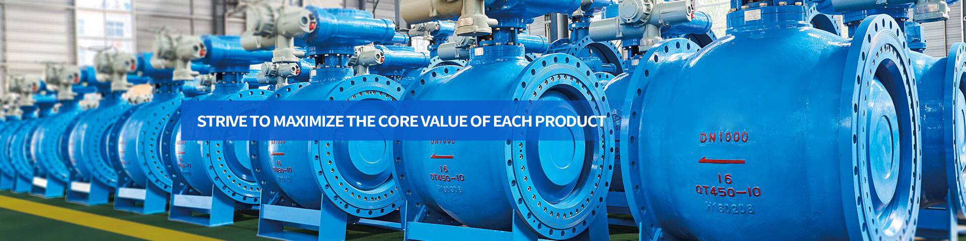
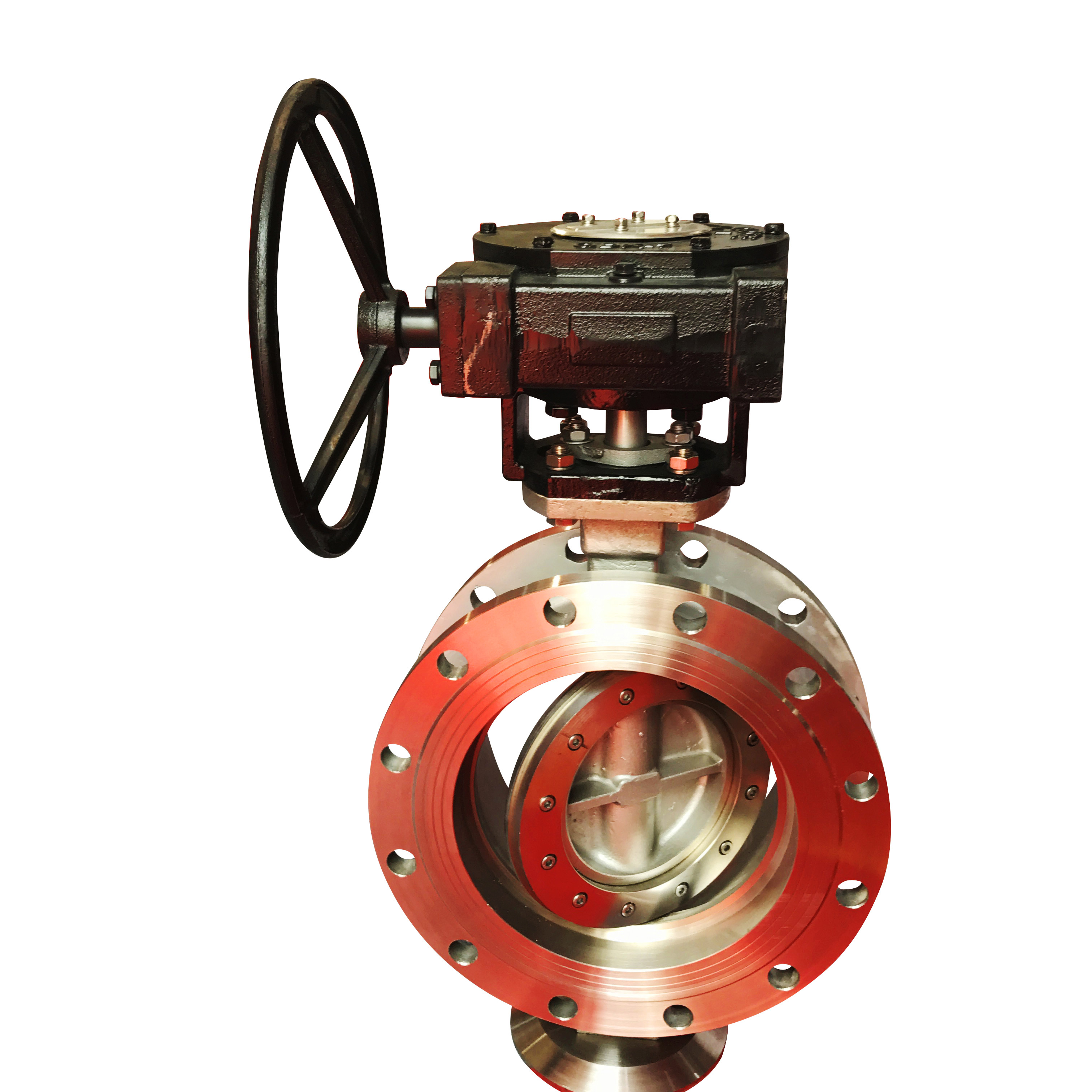
 Location:Home > Product Center > Butterfly Valve > D971F46Electric fluorine lined wafer butterfly valve
 Telephone:
0577-67975099
Telephone:
0577-67975099
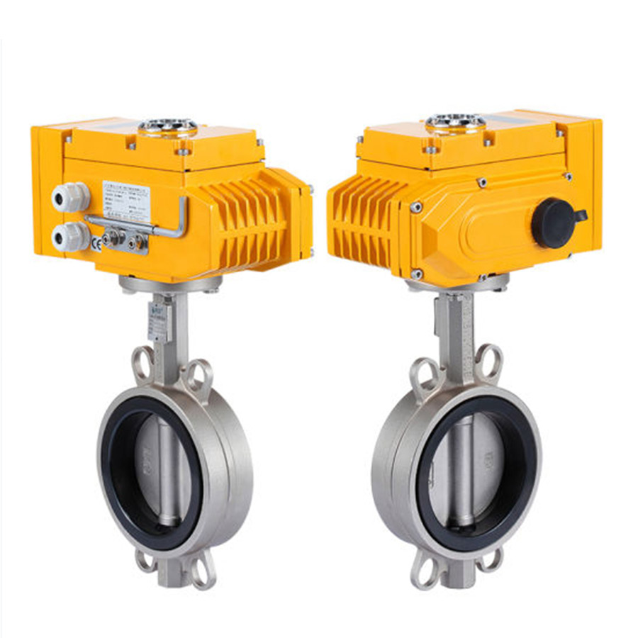
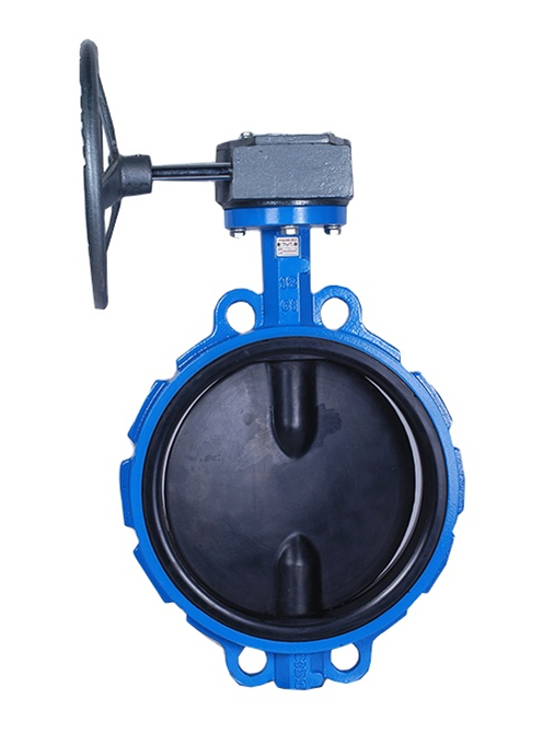
D971F46The electric fluorine lined double clip butterfly valve adopts fluorine lined plastic lining butterfly plate with spherical sealing surface and silicone rubber gasket at the base of valve seat to adjust the sealing performance of the valve; the valve is easy to operate, tight sealing performance and long service life.
D971F46The electric fluorine lined double clip butterfly valve adopts fluorine lined plastic lining butterfly plate with spherical sealing surface and silicone rubber gasket at the base of the valve seat to adjust the sealing performance of the valve. The valve is easy to operate, with tight sealing performance and long service life. It can be used for fast cutting off or regulating flow. It is suitable for the occasions requiring reliable sealing and good regulating characteristics. The valve body adopts split type, and the sealing of the current end of the valve shaft is controlled by adding fluorine rubber to the rotating base surface between the butterfly plate and the valve seat, so as to achieve compact structure, beautiful appearance, reasonable process and reliable performance. Ensure that the valve shaft does not contact with the fluid medium in the cavity, so it is very convenient to replace the valve shaft, and the valve can be completed without detaching from the pipeline. The products are widely used in the transportation of liquid and gas (including steam) in various types of industrial pipelines, especially for those with severe corrosive media, such as sulfuric acid, hydrofluoric acid, phosphorus, acid, chlorine, strong alkali, aqua regia, etc.
D971F46Material list of main parts and components of electric fluorine lined wafer butterfly valve
| Serial number | Part name | Gray cast iron | cast steel | Stainless and acid resistant cast steel | Ultra low carbon stainless and acid resistant cast steel | ||
| Z | C | P | R | PL | RL | ||
| 1 | Body / bonnet | HT250 | WCB | CF8 | CF8M | CF3 | CF3M |
| 2 | Disc | WCB | 35 | CF8 | CF8M | CF3 | CF3M |
| 3 | Stem | 1Cr13 | 2Cr13 | 1Cr18Ni9Ti | 1Cr18Ni12Mo2Ti | 00Cr18Ni10 | 000Cr17Ni14Mo2 |
| 4 | Liner / seat | PTFE(F4),PCTEF(F3),FEP(F46),PFA(可溶F4),PP,PO | |||||
| 5 | seal ring | FPM(Fluororubber) | FPM(Fluororubber)) | ||||
| 6 | Elastic strip (PAD) | Si(silicon rubber) | Si(silicon rubber) | ||||
| 7 | Adjusting positioning seat | 0Cr18Ni9 | 0Cr18Ni9 | 1Cr18Ni9Ti | 1Cr18Ni12Mo2Ti | 00Cr18Ni10 | 00Cr17Ni14Mo2 |
| 8 | Fastening bolt | 35 | 35 | 1Cr17Ni2 | 1Cr17Ni2 | 1Cr18Ni9Ti | 1Cr18Ni9Ti |
| 9 | Nut | 45 | 45 | 0Cr18Ni9 | 0Cr18Ni9 | 0Cr18Ni9 | 0Cr18Ni9 |
| 10 | Operating handle | ZL101 | |||||
| Nominal diameter | L | D | D1 | D2 | f | b | Z-φd | D | D1 | D2 | f | b | Z-φd | |
| DN(mm) | NPS(inch) | PN1.0MPa | PN1.6MPa | |||||||||||
| 40 | 3/2 | 33 | 145 | 110 | 85 | 3 | 18 | 4-φ18 | 145 | 110 | 85 | 3 | 18 | 4-φ18 |
| 50 | 2 | 43 | 160 | 125 | 100 | 3 | 20 | 4-φ18 | 160 | 125 | 100 | 3 | 20 | 4-φ18 |
| 65 | 5/2 | 46 | 180 | 145 | 120 | 3 | 20 | 4-φ18 | 180 | 145 | 120 | 3 | 20 | 4-φ18 |
| 80 | 3 | 46 | 195 | 160 | 135 | 3 | 22 | 4-φ18 | 195 | 160 | 135 | 3 | 22 | 8-φ18 |
| 100 | 4 | 52 | 215 | 180 | 155 | 3 | 22 | 8-φ18 | 215 | 180 | 155 | 3 | 24 | 8-φ18 |
| 125 | 5 | 56 | 245 | 210 | 185 | 3 | 24 | 8-φ18 | 245 | 210 | 185 | 3 | 26 | 8-φ18 |
| 150 | 6 | 56 | 280 | 240 | 210 | 3 | 24 | 8-φ23 | 280 | 240 | 210 | 3 | 28 | 8-φ18 |
| 200 | 8 | 60 | 335 | 295 | 265 | 3 | 26 | 8-φ23 | 335 | 295 | 265 | 3 | 30 | 12-φ23 |
| 250 | 10 | 68 | 390 | 350 | 320 | 3 | 28 | 12-φ23 | 405 | 355 | 320 | 3 | 32 | 12-φ25 |
| 300 | 12 | 78 | 440 | 400 | 368 | 3 | 28 | 12-φ23 | 460 | 410 | 375 | 4 | 34 | 12-φ25 |
| 350 | 14 | 78 | 500 | 460 | 428 | 4 | 30 | 16-φ23 | 520 | 470 | 435 | 4 | 38 | 16-φ25 |
| 400 | 16 | 102 | 565 | 515 | 482 | 4 | 32 | 16-φ25 | 580 | 525 | 485 | 4 | 40 | 16-φ30 |
| 450 | 18 | 114 | 615 | 565 | 532 | 4 | 32 | 20-φ25 | 640 | 585 | 545 | 4 | 44 | 20-φ30 |
| 500 | 20 | 127 | 670 | 620 | 585 | 4 | 34 | 20-φ25 | 705 | 650 | 608 | 4 | 46 | 20-φ34 |
| 600 | 24 | 154 | 780 | 725 | 685 | 5 | 36 | 20-φ30 | 840 | 770 | 718 | 5 | 54 | 20-φ41 |
| 700 | 28 | 165 | 895 | 840 | 800 | 5 | 40 | 24-φ30 | 910 | 840 | 788 | 5 | 54 | 24-φ41 |
| 800 | 32 | 190 | 1010 | 950 | 905 | 5 | 44 | 24-φ34 | 1020 | 950 | 898 | 5 | 54 | 24-φ41 |
| 900 | 36 | 203 | 1110 | 1050 | 1005 | 5 | 46 | 28-φ34 | 1120 | 1050 | 998 | 5 | 54 | 28-φ41 |
| 1000 | 40 | 216 | 1220 | 1160 | 1115 | 5 | 50 | 28-φ34 | 1255 | 1170 | 1110 | 5 | 60 | 28-φ48 |
| 1200 | 48 | 254 | 1450 | 1380 | 1325 | 5 | 56 | 32-φ41 | ||||||
1. Before installation, check whether the specification, pressure, temperature and corrosion resistance of butterfly valve meet the use requirements. Check whether the parts are damaged or loose.
2. The butterfly valve can be installed on the pipeline at any angle and should be closed; when welding the pipe flange, the valve sealing port should be blocked with a plate to prevent particles and sundries from damaging the sealing surface. After welding, take down the valve, clean the valve sealing surface and pipe cavity, and then install the fixed valve.
3. Please pay attention to the pressure bearing direction when the valve is closed.
4. Before installation, the sealing surface (sealing surface at both ends, sealing surface of butterfly plate and sealing surface of valve seat) shall be thoroughly cleaned to remove dust and dirt.
5. Before installation, the butterfly valve should be air tested, and the opening and closing position should be flexible, and the opening and closing position should be consistent with the position indicated by the pointer.
6. Manual operation, clockwise is off, counter clockwise is on, pointer indication is in place, it is not allowed to open and close the valve with additional force.
7. During the pressure test of the valve, it is not allowed to use single flange for installation and pressure test, but double flange installation and pressure test must be adopted. The test pressure shall comply with GB / T13927-92.
8. The bolts shall be tightened symmetrically and alternately instead of separately.
9. The limit screw has been adjusted before delivery, so it is not allowed to adjust it easily. If the configuration of driving device is electric or pneumatic, please refer to the manual of supporting drive device.
10. When the electric butterfly valve leaves the factory, the opening and closing stroke of the control mechanism has been adjusted. In order to prevent the wrong direction when the power supply is connected, the user should first manually open it to the half open position before connecting the power for the first time, and then press the inching switch to check that the direction of the indicator wheel is consistent with the opening direction of the valve.
11. If the valve is found to be open and closed abnormally, the cause shall be found out for repair and elimination, so as to prevent the valve from being damaged due to opening and closing by means of applying force.

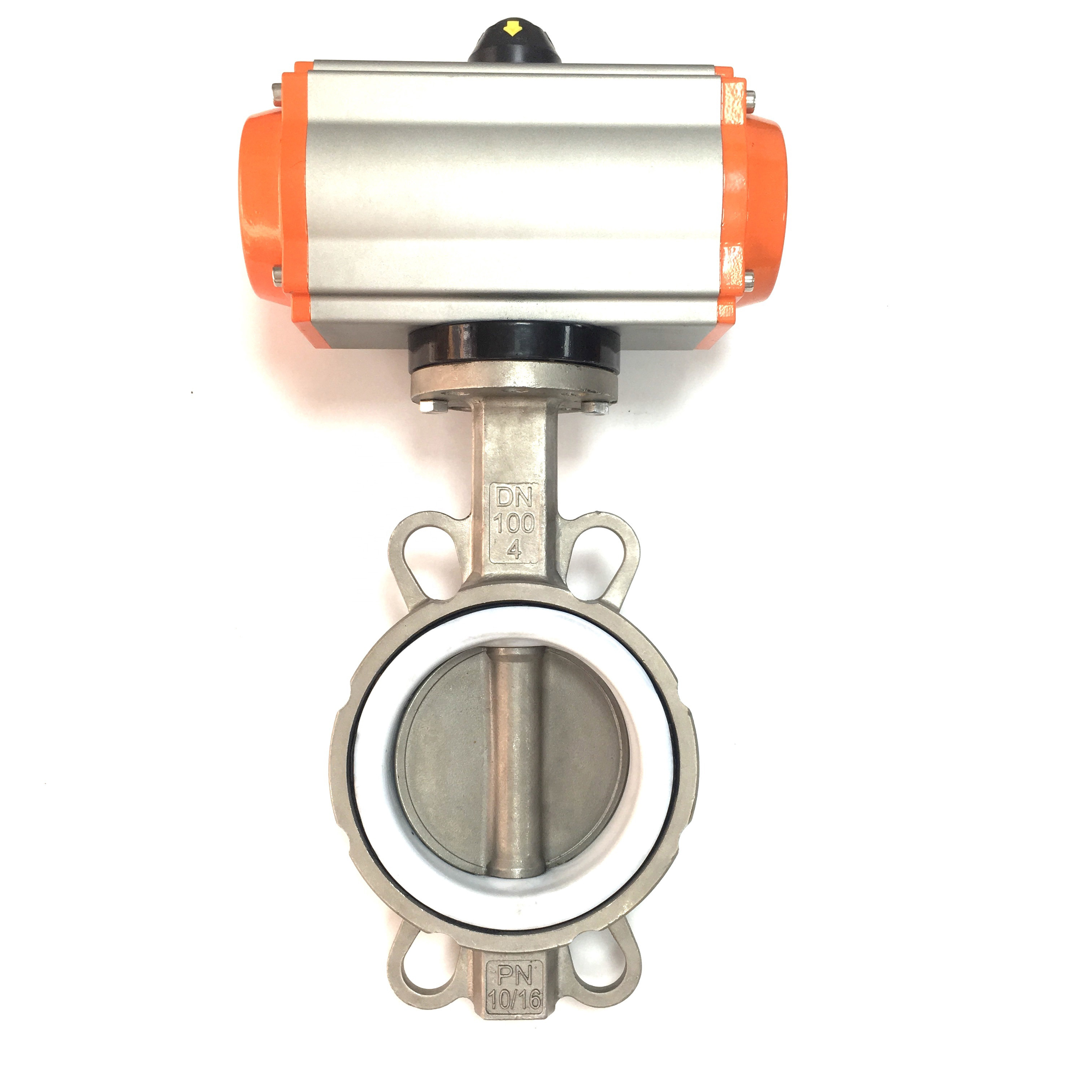
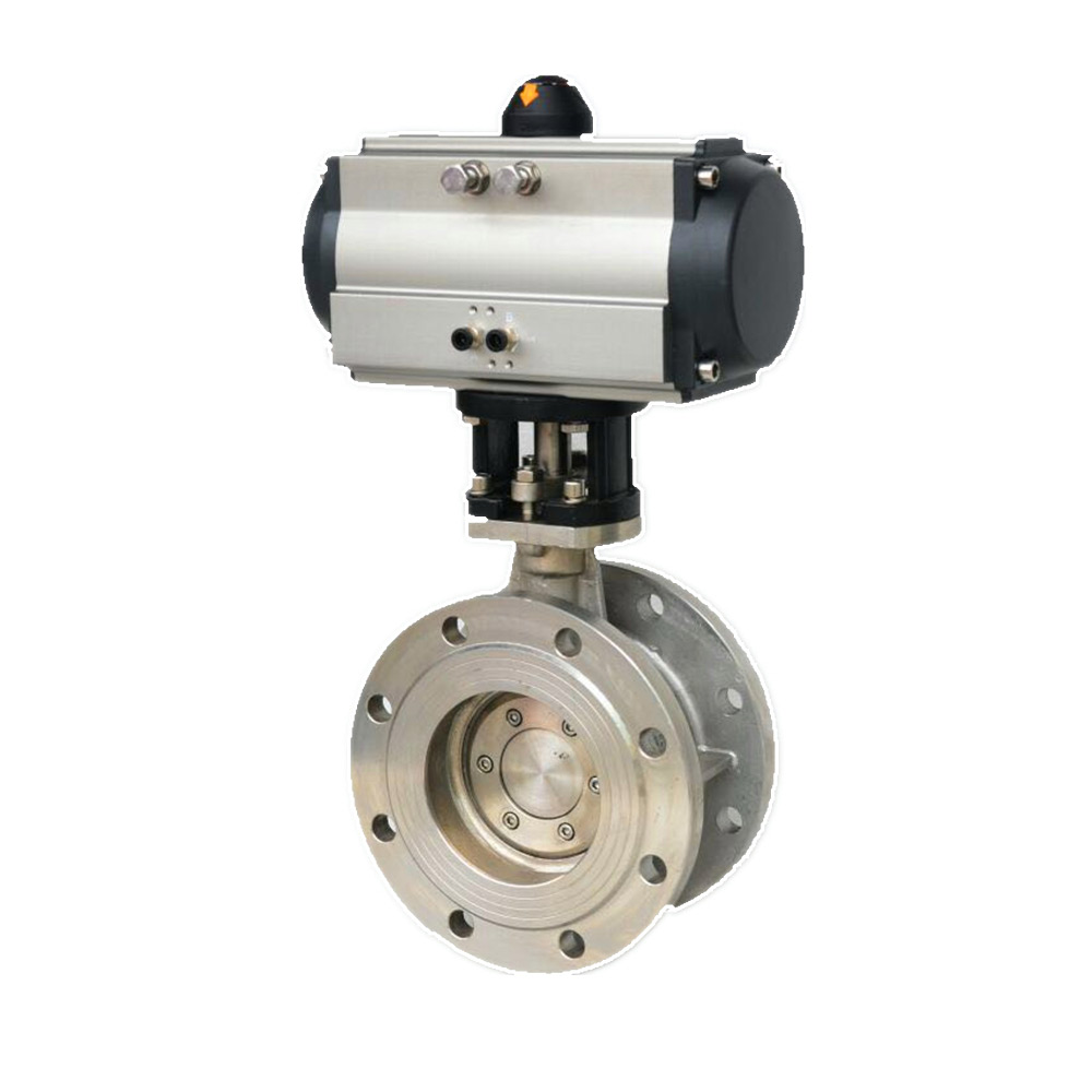
D641HPneumatic flange type hard seal butterfly valvePN16~PN40
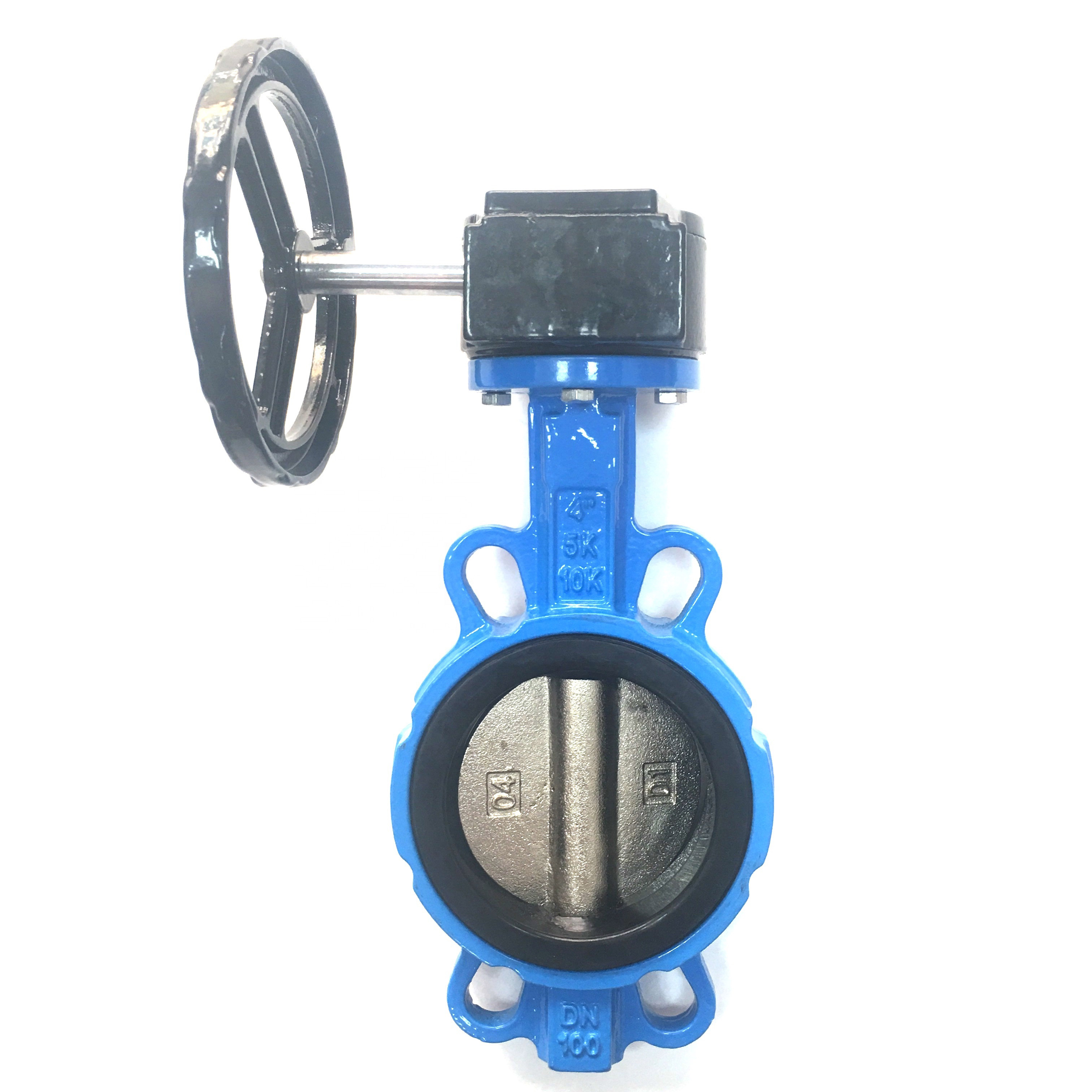
D371XDouble clip worm gear soft seal butterfly valvePN6~PN16
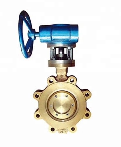
D373F、D373WType Ni Al Bronze double clip hard seal butterfly valve
D341J-16Worm gear flange type half lined rubber butterfly valve
D371J-10Worm gear double clip full rubber lined butterfly valve
蝶阀的产品分类介绍
蝶阀又叫翻板阀,是一种结构简单的调节阀,同时也可用于低压管道.....常用阀门材料允许使用压力明细介绍
常用阀门材料允许使用压力明细说明。常用阀门材质国家标准代号分类
常用阀门材质国家标准代号分类有那些,上欧为您做准确说明,请参.....What is the name.....
The name of the organization t.....Main technical r.....
The main technical requirement.....Bill of material.....
1: Screw plug: Bronze / stainl.....Set up a new ben.....
Full flow streamline design, t.....General technica.....
The adjustment of piston type .....Fast Navigation
Product Line
Recommended Products
Technical Support
Copyright:Shangou Valve Co.,Ltd Record No:; Sitemap
Friendship Links: SenAu Product website