0577-67975099
 QQ
QQ WeChat
 邮箱
邮箱
Telephone:
0577-67975099
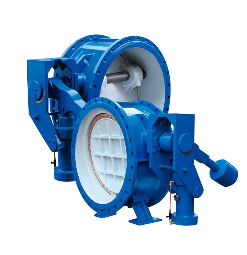
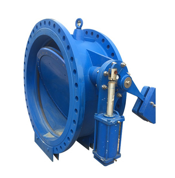
 Location:Home > Product Center > Check Valve > HD742X/HD743HHeavy hammer hydraulic control slow closing check valve
 Telephone:
0577-67975099
Telephone:
0577-67975099
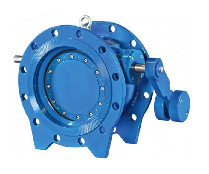
Hydraulic control slow closing check butterfly valve is an advanced pipeline control equipment at home and abroad. It is mainly installed at the inlet of hydraulic turbine of hydropower station and used as the inlet valve of water turbine; or it is installed at the outlet of water conservancy, electric power, water supply and drainage pump stations to replace the function of check valve and gate valve. When working, the valve cooperates with the pipeline host, according to the hydraulic transition process principle, through the preset opening and closing procedures, effectively eliminates the pipeline water hammer, realizes the reliable cut-off of the pipeline, and plays a role in protecting the safety of the pipeline system.
Hydraulic control slow closing check butterfly valve is an advanced pipeline control equipment at home and abroad. It is mainly installed at the inlet of hydraulic turbine of hydropower station and used as the inlet valve of water turbine; or it is installed at the outlet of water conservancy, electric power, water supply and drainage pump stations to replace the function of check valve and gate valve. When working, the valve cooperates with the pipeline host, according to the hydraulic transition process principle, through the preset opening and closing procedures, effectively eliminates the pipeline water hammer, realizes the reliable cut-off of the pipeline, and plays a role in protecting the safety of the pipeline system.
Nominal diameter: DN 150 ~ dn3500
Nominal pressure: pn2.5 ~ PN40
Applicable media: water, sea water, sediment water, oil, etc
Medium temperature: ≤ 80 ℃
Valve opening time: 10 ~ 120 seconds (adjustable)
Fast closing time: 1.5 ~ 30 seconds (adjustable)
Slow closing time: 6 ~ 120 seconds (adjustable)
Quick closing angle: 70 °± 10 °
Slow closing angle: 20 °± 10 °
Zui small flow resistance coefficient in full open state: 0.1
Optional control power supply: AC220 V, DC 220 V, DC 110 V, DC 24 v
It can replace the function of the original electric gate valve and check valve at the outlet of the water pump, and the mechanical, electrical and hydraulic systems are integrated as a whole to reduce the floor space and infrastructure investment.
2. The electro-hydraulic control function is complete, which can be used as an independent system for on-site debugging and control without additional configuration; it can also be used as an equipment unit of distributed control system (DCS), which is centrally managed by the central computer through 1 / 0 channel, and realizes linkage operation with water pump, turbine, bypass valve and other pipeline equipment; it is also equipped with manual function without power supply The valve can also be opened and closed manually to meet the requirements of valve debugging and control under special working conditions.
3. It has good controllability, wide adjustment range and strong adaptability. The electro-hydraulic control system is equipped with multiple adjusting nodes, which can be set according to different pipeline control requirements to ensure that when the conditions of opening and closing the valve are met, the valve can and can be opened automatically according to the preset time and angle and closed in two stages, fast and slow. It can effectively eliminate the destructive water hammer, prevent the runaway accidents of pumps and turbine units, reduce the pressure fluctuation of the pipe network system, and ensure the safe and reliable operation of the equipment.
4. The sealing pair of the main valve is of three eccentric metal seal or double eccentric rubber seal structure, which is easy to open and close, and has an additional eccentricity to make the valve have good self closing and self sealing performance. The middle and small diameter butterfly plate is designed as streamline flat plate structure, while the large diameter butterfly plate is designed with double plate truss structure, which has small displacement and smooth flow. The flow resistance coefficient of valve is only 0.1 ~ 0.6, which is far less than the flow resistance coefficient of check valve (1.7 ~ 2.6), so the energy saving effect is obvious.
| Part name | Materials |
| Valve body | Gray cast iron, ductile iron, carbon steel |
| Sphenoid plate | Gray cast iron, ductile iron, carbon steel |
| Valve shaft | Stainless steel, carbon steel |
| Sealing surface of valve body | Copper alloy, stainless steel |
| Sealing ring of butterfly plate | High quality nitrile rubber, stainless steel / flexible graphite lamination |
| Sliding bearing | Filling material |
| filler | V-ring, flexible graphite |
| Wall board | Carbon steel |
|
Nominal diameterDN(mm) |
150~ 4000 |
|
|
Nominal pressure classPN(MPa) |
0.25 ~ 4.0 |
|
|
Test pressure Ps(MPa) |
Sealing |
1.1×PN |
| Strength | ||
|
working pressure(MPa) |
≤1.0×PN |
|
|
Medium temperature(℃) |
≤80 |
|
| Suitable medium | Clear water, sea water, sediment water, oil, etc | |
注:1.1 Mpa=10.2kgf/cm2 2、用于水电站时,密封试验压力可按电站zui高静水头计算值。
2、特殊参数:
|
公称通径 |
∠1000 |
≥1000 |
|
|
开阀时间(可调) |
10~60秒 |
20~120秒 |
|
|
关阀时间(可调) |
快关 |
1.5~15秒 |
2.5~25秒 |
|
慢关 |
2.5~60秒 |
6~90秒 |
|
|
关阀角度(可调) |
快关 |
70±10度 |
70±10度 |
|
慢关 |
20±10度 |
20±10度 |
|
|
zui小流阻系数 |
0.1 |
||
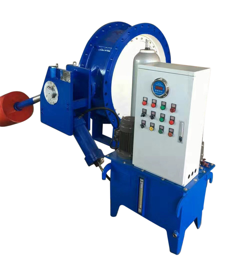
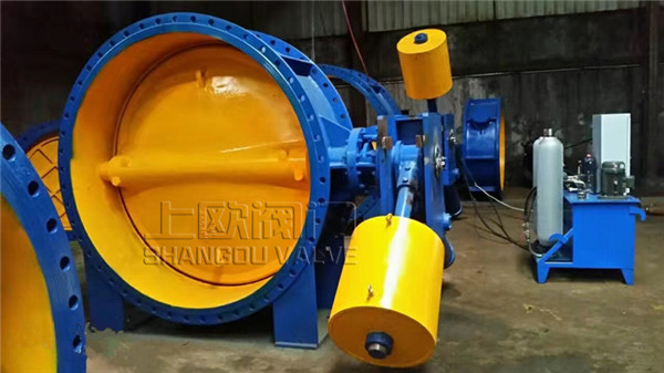
1. This product is mainly composed of valve body, transmission mechanism, hydraulic device, electrical control box and other parts. 1. The valve body is composed of valve body, butterfly plate, valve rod, sliding bearing, seal and other parts.
2. The valve body of heavy hammer hydraulic control slow closing check butterfly valve is horizontal arrangement, and the valve shaft is arranged with half shaft.
3. The transmission mechanism is mainly composed of hydraulic cylinder, rocker arm, supporting wallboard, hammer, lever (locking type and locking cylinder) and other connecting and transmission parts.
4. The transmission mechanism is generally installed in the forward direction or in the reverse direction according to the user's requirements (that is, the transmission mechanism is located on the other side of the valve).
5. The hydraulic station includes oil pump unit, manual pump, accumulator, solenoid valve, overflow valve, flow control valve, stop valve, hydraulic manifold block, oil tank and other components.
6. In the heavy hammer automatic pressure maintaining system, the accumulator is used as the system pressure compensation; in the locking type heavy hammer type automatic pressure maintaining system, the accumulator is used as the system pressure compensation and the locking cylinder is released. The flow control valve regulates the switching time, the relief valve is used as the safety valve of the system, and the stop valve is used as the pressure relief of the whole system.
7. The characteristics of the solenoid valve in hydraulic system are generally positive action type, that is, the solenoid valve is powered on butterfly valve to open the valve and power off butterfly valve to close the valve; on the contrary, it is the reaction type, that is, the solenoid valve de energized butterfly valve opens and the power on butterfly valve closes. The conventional matching electromagnetic directional valve is positive action type, and the reaction type shall be specified when ordering.
8. The hydraulic system and valve body can be integral or split installation. If the user does not make any special instructions, it is split installation.
The main logic element of the valve electrical control system is PLC intelligent control type, which is divided into the following working conditions: open valve centrifugal pump condition (including centrifugal mixed flow pump): start the pump first, extend the predetermined time and then open the valve, or open the pump valve at the same time. Working condition of open valve axial flow pump (including axial mixed flow pump): the pump valve is opened at the same time, or the valve is opened to a certain angle, and then the pump is started.
6.1 turn the transfer switch to the "ground" position by local control
6.1.1 open the valve, close the air switch, connect the pump power supply AC380V, control the uninterruptible power supply DC24 V, and the power indicator light is on. Turn the "change-over switch" to the right position of the control source, press the valve opening button on the local control box, the valve opening indicator light will be on, the oil pump will start, the valve will open at the set speed, until the fully open position (full open indicator light is on), the valve opening action will be stopped automatically, and the valve opening indicator light will be off automatically. The valve opening time can be adjusted by opening the flow of the flow control valve. Different valve opening times can be achieved to adapt to the actual working conditions. The time adjustment range is shown in the table above.
6.1.2 automatic pressure maintaining: when the valve is opened in place, the automatic pressure maintaining unit of the control system will start automatically, and the oil pump will automatically charge the system. When the pressure reaches the high pressure of pressure relay (14MPa), the oil pump stops. In the future, the automatic pressure maintaining function will be effective when the valve is fully open. That is, when the system pressure is lower than the low-pressure 10MPa set by the pressure relay, the oil pump will start automatically; when the system pressure increases to 14MPa, the oil pump will stop automatically to ensure that the valve is fully opened and the heavy hammer is lifted.
6.1.3 to close the valve, press the valve closing button, and the valve closing indicator light is on, then the valve will close according to the set speed depending on the potential energy of the heavy hammer (the oil pump will not start), until the fully closed position (full closing indicator light is on), the valve closing action will be automatically stopped, and the valve closing indicator light will be off. The valve closing is divided into two stages: fast closing and slow closing. The fast closing speed is adjusted and the fast closing speed control valve is adjusted. The slow closing speed is adjusted and the slow closing regulating valve is closed slowly. The adjustment range is shown in the table above.
6.1.4 during the opening and closing process of the valve, press the stop button to stop the valve at any position in the middle.
6.2 in remote control, the transfer switch is turned to "remote" position, and the remote indicator light is on.
6.2.1 open the valve, start the pump first, then open the valve, and start the water pump in the central control room. After the preset time is delayed, the normally open contact of the water pump control relay is closed, and the valve is opened and maintained according to the predetermined procedure. By adjusting the delay preset time to zero, the pump can be started at the same time. Open the valve first, then start the pump. Press the remote valve opening button to start the oil pump, and then the valve will open. When the valve is opened to a certain angle (15 °), the pump start stroke switch is closed, and the signal is sent out, and the water pump is started in the central control room. At the same time, the valve opening button sends the pump start signal, which can also realize the pump and valve start at the same time.
6.2.2 automatic pressure maintaining: when the valve is in the fully open state, enter the automatic pressure maintaining state like the local control to ensure that the valve is in the full open state and lift the heavy hammer.
6.2.3 close the valve and the pump valve is normal. At the same time, the water pump is shut down. The solenoid valve is powered on for reversing, and the valve is closed according to the predetermined procedure. Close the valve first and then stop the pump. 6.2.4 linkage power loss protection presses the remote valve closing button to close the valve. When the valve is closed to a certain angle (75 °), the travel switch is pressed to send a signal, and the remote control room stops the water pump. The electric control equipment is connected with DC24 V standby power supply. When the conventional power supply loses power, the standby power supply is automatically connected to ensure the automatic operation of the valve. When the water pump stops, the butterfly valve will be closed at the same time.
6.2.5 the remote monitoring and control system can receive remote valve opening, closing, valve stopping and pump status information, and output various signals for remote DCS monitoring, mainly including valve position signal, remote status signal, oil pump status signal, motor overload, valve opening timeout signal, valve position analog signal, etc., and the signals are passive dry contact switching signal.
6.3 in case of power failure of manual operation power supply, the valve can be opened by shaking the hand pump. Open "10 normally closed globe valve" when manually closing, and close "10 normally closed globe valve" after closing valve in place; open "09 normally closed globe valve" and close it after pressure oil is drained out; "08 normally open globe valve" is normally open, if "06 solenoid ball valve" fails, it needs to be repaired, close "08 normally open stop valve" for maintenance Ring valve use (can be hydraulic or manual valve opening, manual closing valve). The manual function is mainly to use the standby power supply to debug the valve, or to close the valve under special circumstances. 1.5 adjustment method for high and low pressure of pressure transmitter: click "control panel" in main menu, click "oil pressure setting" in submenu, and then click "upper limit" and "lower limit" in submenu to pop up a number box and set it by yourself. It has been set at the factory, do not change it at will.
7、 Hoisting and commissioning maintenance
7.1 when lifting and transporting, it is not allowed to turn over or put upside down. After unpacking, the butterfly valve shall be transported by crane, and the balance position shall be selected among the four lifting points.
7.2 when the product is stored for a long time, put it in a dry place, close both ends of the inlet and outlet, and coat the sealing surface with antirust oil. During temporary parking, auxiliary support can be added at the position of external wall panel to maintain stability. If it is not installed for half a year, the hydraulic system must be cleaned and replaced with oil.
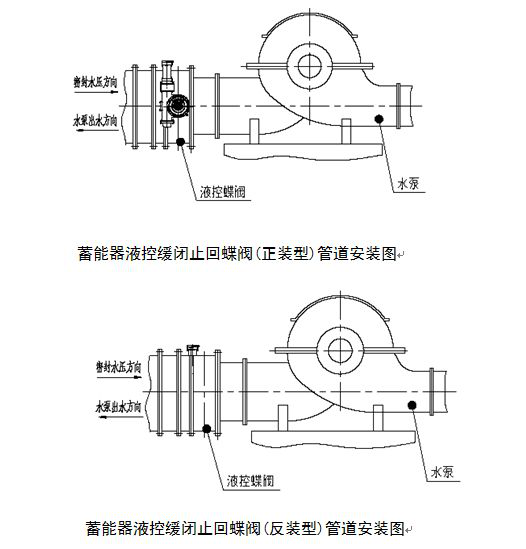
7.3 before installation, it is necessary to check whether the parameters of the valve name plate meet the use requirements, clean the valve channel and butterfly plate, check whether there is damage at each part, and whether the connecting bolts of all parts are tightened. Confirm the relative orientation of the hydraulic transmission system and the water pump outlet pipe as shown in the figure, and install the valve at the water pump outlet. The level of butterfly plate shall be corrected on the basis of installation
常用阀门材料允许使用压力明细介绍
常用阀门材料允许使用压力明细说明。常用阀门材质国家标准代号分类
常用阀门材质国家标准代号分类有那些,上欧为您做准确说明,请参.....What is the name.....
The name of the organization t.....Main technical r.....
The main technical requirement.....Bill of material.....
1: Screw plug: Bronze / stainl.....Set up a new ben.....
Full flow streamline design, t.....General technica.....
The adjustment of piston type .....Fast Navigation
Product Line
Recommended Products
Technical Support
Copyright:Shangou Valve Co.,Ltd Record No:; Sitemap
Friendship Links: SenAu Product website